Blend Topology
The ACIS blending algorithm works on a network of edges and vertices. The edges and vertices presented for blending should not form disjoint networks. Each of the edges and vertices has an associated blend radius or chamfer distance. The radii in the network do not have to be the same. Blends are created, evaluated, and attached with a high degree of precision. Wherever possible, analytic surfaces are used.
Edges are characterized by the continuity between the two faces meeting at the edge and by the convexity of the faces along the edge. They are smooth if their two faces meet with tangent plane (G1) continuity; else, they are non-smooth. Blending operations may fail on non-G1 surfaces. Edges are further characterized as being convex or concave. Edges must have the same continuity and convexity along their entire domain of definition.
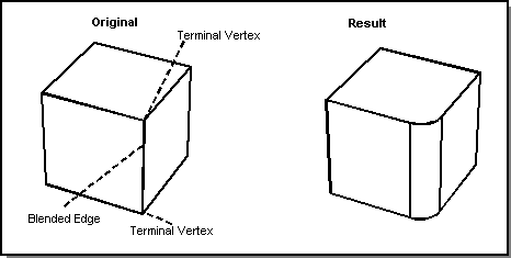
Vertices are characterized by the number of blended edges meeting at the vertex. A vertex is a terminal vertex if exactly one blended edge ends at the vertex. The following figure shows terminal vertices.

Figure. Terminal Vertex
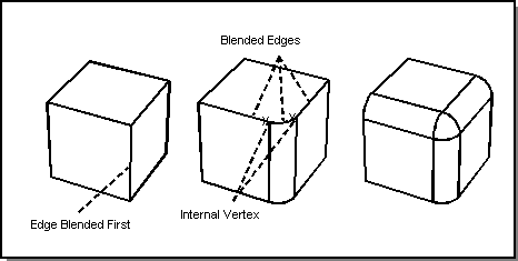
A vertex is an internal vertex if two or more edges coming into the vertex are blended. The following figure shows internal vertices. In this example, blending one edge at the vertex creates a smooth connection between the other two edges, which are then blended as a smooth sequence.

Figure. Internal Vertex
[Top]
© 1989-2007 Spatial Corp., a Dassault Systèmes company. All rights reserved.