Creating Geometry with Laws
Using law_spl_sur and law_int_cur classes, the APIs api_curve_law, api_edge_law, and api_face_law create curves or surfaces from laws. Associated Scheme extensions are available for these functions. Laws are incorporated into wire offsetting and sweeping for creating geometry.
Creating Curves
An edge can be created that uses a law to define its path.
Scheme Example
| (define my_law (law "(20*sin(x)+x^2-10)*.2")) ;; my_law (law:nroot my_law -10 10) ;; (-3.14655291240276 0.508720501792063 ;; 3.13209276518624 5.23133412213485) (define my_veclaw (law "vec(x,law,0)" my_law)) ;; my_veclaw (define fedge(edge:law my_veclaw -10 10)) ;; fedge (define x_axis(edge:law "vec(x,0,0)" -10 10)) ;; x_axis (define y_axis(edge:law "vec(0,x,0)" -10 20)) ;; y_axis |
Creating Surfaces
Laws have the law_spl_sur class (derived from spl_sur) and the law_int_cur class (derived from int_cur). These two classes allow you to create a surface or a curve directly from the appropriately dimensioned law. These law curves or surfaces can be used in subsequent operations, such as sweeping, Booleans, etc.
Scheme Example
| (define my_s1(face:law "vec(x,y,sin(x)*cos(y))" -10 10 -10 10)) ;; my_s1 (define my_sb(sheet:face my_s1)) ;; my_sb (sheet:2d my_sb) ;; #[entity 3 1] (define my_e1(edge:linear (position 7 7 -10)(position 7 -7 -10))) ;; my_e1 (define my_e2(edge:linear (position 7 -7 -10) (position -7 -7 -10))) ;; my_e2 (define my_e3(edge:linear (position -7 -7 -10) (position -7 7 -10))) ;; my_e3 (define my_e4(edge:linear (position -7 7 -10)(position 7 7 -10))) ;; my_e4 (define my_profile(wire-body (list my_e1 my_e2 my_e3 my_e4))) ;; my_profile (define my_path(edge:linear (position 0 0 -10)(position 0 0 10))) ;; my_path (define my_face(car(entity:faces my_sb))) ;; my_face (define my_surf(surface:from-face my_face)) ;; my_surf (entity:delete my_sb) ;; () (define my_opt(sweep:options "to_face" my_surf)) ;; my_opt (define my_sweep(sweep:law my_profile my_path my_opt)) ;; my_sweep (entity:delete my_path) ;; () |
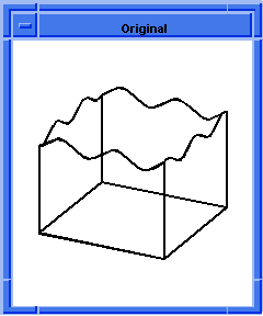
Figure. Law Surface
The following example illustrates how a face created with a law can be used in subsequent operations. First, a face is created with the law z=sin(x)*cos(y), then a profile is swept to the face, then a hemisphere is removed from the surface. The law surface is then extended with a local operation (move faces).
Scheme Example
| ; Create the face
(define s1(face:law vec(x,y,sin(x)*cos(y)) -10 10 -10 10)) ;; s1 ; s1 => #[entity 2 1] (define sb(sheet:face s1)) ;; sb ; sb => #[entity 3 1] (sheet:2d sb) ;; #[entity 3 1] ; Create a profile (define my_edges (list (edge:linear (position 7 7 -10) (position 7 -7 -10)) (edge:linear (position 7 -7 -10) (position -7 -7 -10)) (edge:linear (position -7 -7 -10) (position -7 7 -10)) (edge:linear (position -7 7 -10) (position 7 7 -10)))) ;; my_edges (define profile(wire-body my_edges)) ;; profile (define path(edge:linear (position 0 0 -10)(position 0 0 10))) ;; path (define face(car(entity:faces sb))) ;; face (define surf(surface:from-face face)) ;; surf (entity:delete sb) ;; () ; Sweep (define opt(sweep:options "to_face" surf)) ;; opt (define sweep(sweep:law profile path opt)) ;; sweep ; sweep => #[entity 8 1] (entity:delete path) ;; () ; Define a sphere and subtract it from the law surface (define sp(solid:sphere (position 0 0 0) 5)) ;; sp (solid:subtract sweep sp) ;; #[entity 8 1] ; Pick the face on the right to extend the faces (lop:move-faces (pick-face) (gvector 10 0 0)) ;; #[entity 8 1] |
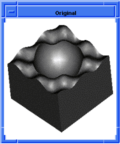
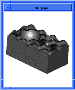
Figure. Scheme Example of Law Surface
Planar Wire Offsetting
Planar wire offsetting can accept laws as the offset distance.
Scheme Example
| (define my_edge (edge:circular (position 0 0 0) 20)) ;; my_edge ; my_edge => #[entity 2 1] (define my_wirebody (wire-body my_edge)) ;; my_wirebody ; my_wirebody => #[entity 3 1] ; Uses a law offset and no twist law. (define my_offset (wire-body:offset my_wirebody "20+10*cos(x*10)")) ;; my_offset ; my_offset => #[entity 4 1] |
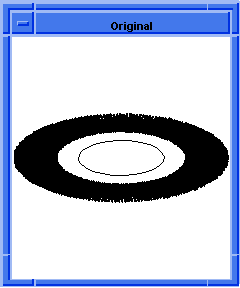
Figure. Planar Wire Offsetting
Nonplanar Wire Offsetting
Non-planar wire offsetting has been built into wire-body:offset as an additional argument for the twist law.
Scheme Example
| ; Create edge 1. (define my_edge1 (edge:circular (position 10 0 0) 10)) ;; my_edge1 => #[entity 2 1] ; Create a wire-body from the edges. (define my_wirebody (wire-body (list my_edge1))) ;; my_wirebody => #[entity 2 1] ; Offset a wire-body outside the original wire-body. ; Uses a constant (law) offset and a twist law. (define my_spiral (wire-body:offset my_wirebody 5 "15*x")) ;; my_spiral => #[entity 3 1] |
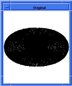
Figure. Non-planar Wire Offsetting
Creating a Helix
Helixes can be created using api_edge_helix. This is part of the Constructors Component. It does not require that the helix be created by offsetting a line with a twist law.
Scheme Example
| ; edge:helix ; Create a helical edge. (define axis_start1 (position 0 0 0)) ;; axis_start1 (define axis_end1 (position 0 0 10)) ;; axis_end1 (define start_dir1 (gvector 1 0 0)) ;; start_dir1 (define radius1 5) ;; radius1 (define thread_distance1 2) ;; thread_distance1 (define helix1 (edge:helix axis_start1 axis_end1 start_dir1 radius1 thread_distance1)) ;; helix1 ; Create another helical edge. (define helix2 (edge:helix (position -20 0 0) (position -20 10 10) (gvector 0 1 0) 5 2 #f)) ;; helix2 ; And one more. (define helix3 (edge:helix (position 20 0 0) (position 20 0 10) (gvector 0 1 0) 5 2 #f)) ;; helix3 ; OUTPUT Example |
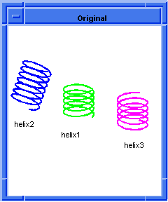
Figure. Helix Examples
Planar Sweeping
Sweeping with laws, such as the sweep:law Scheme extension, encompasses the functionality of many of the other sweep extensions. Sweeping along a planar path can accept a law as one of the arguments, such as the offset distance.
The following example sweeps a circular profile along a linear path. It uses the minimum rotation law by default for the orientation of the profile. However, as it sweeps, it uses a draft law to create a vaselike appearance.
Scheme Example
| (option:set "u_par" 10) ;; -1 (option:set "v_par" 10) ;; -1 (option:set "cone_par" #t) ;; #f (option:set "sil" #f) ;; #t (define my_edge (edge:linear (position 0 0 0) (position 0 0 40))) ;; my_edge ; my_edge => #[entity 2 1] (define my_path (wire-body my_edge)) ;; my_path ; my_path => #[entity 3 1] (define my_eprofile (edge:circular (position 0 0 0) 10)) ;; my_eprofile ; my_eprofile => #[entity 4 1] (define my_profile (wire-body my_eprofile)) ;; my_profile ; my_profile => #[entity 5 1] (define my_vase (sweep:law my_profile my_path (sweep:options "draft_law" "10*sin(x/2)"))) ;; my_vase ; my_vase => #[entity 6 1] |
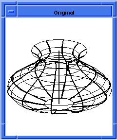
Figure. Sweeping a Vase
Nonplanar Sweeping
Sweeping with laws, such as the sweep:law Scheme extension, encompasses the functionality of many of the other sweep extensions. Sweeping is covered in more detail in another section of the ACIS documentation.
The important aspects of sweeping to note are:
- The profile to be swept needs to be a planar wirebody.
- The path can be non-planar.
- The profile needs to be perpendicular to the path at the starting point of the path.
- The orientation of the profile as it is swept along a non-planar path needs to be specified.
ACIS uses rails for orienting the profile along a non-planar path. There are three main techniques for defining the rails.
- Minimum Rotation
- Requires that a direction for the first rail be specified. A vector field is then created along the path such that the rail vectors are perpendicular to the path and rotate as little as possible with respect to the neighboring rail vectors. This is the default.
- Frenet
- Creates a vector field whose rail vectors are perpendicular to the path and point in direction of curvature.
- Userdefined
- Can be any valid law definition. The vector field that is created should have vector rails perpendicular to the path, but their direction with respect to the other rails is determined by the user-defined law.
When sweeping along a planar path using minimum rotation, the rail vectors all point in the same direction. If the path is non-planar, the resulting body exhibits torque elements.
The following example sweeps a surface along a non-planar path. It uses the minimum rotation rail law to specify how the surface orients itself on the path.
Scheme Example
| ; sweep:law ; Create a sweep path from points (define my_plist (list (position 0 0 0) (position 10 0 0)(position 10 10 0) (position 10 10 10))) ;; my_plist (define my_start (gvector 1 0 0)) ;; my_start ; my_start => #[gvector 1 0 0] (define my_end (gvector 0 0 1)) ;; my_end ; my_end => #[gvector 0 0 1] (define my_path (edge:spline my_plist my_start my_end)) ;; my_path ; my_path => #[entity 2 1] (define my_law (law "cur(edge1)" my_path)) ;; my_law ; my_law => #[law "CUR(EDGE1)"] (define my_rail (law "minrot(law1,vec(0,-1,0))" my_law)) ;; my_rail ; my_rail => #[law "MINROT(CUR(EDGE1),VEC(0,-1,0),0,30)"] (define my_edge1 (edge:linear (position 0 1 1) (position 0 1 -1))) ;; my_edge1 ; my_edge1 => #[entity 3 1] (define my_edge2 (edge:linear (position 0 1 -1) (position 0 -1 -1))) ;; my_edge2 ; m_edge2 => #[entity 4 1] (define my_edge3 (edge:linear (position 0 -1 -1) (position 0 -1 1))) ;; my_edge3 ; my_edge3 => #[entity 5 1] (define my_edge4 (edge:linear (position 0 -1 1) (position 0 1 1))) ;; my_edge4 ; my-edge4 => #[entity 6 1] (define my_profile (wire-body (list my_edge1 my_edge2 my_edge3 my_edge4))) ;; my_profile ; my_profile => #[entity 7 1] (define my_sweep (sweep:law my_profile my_path (sweep:options "rail_law" my_rail))) ;; my_sweep ; my_sweep => #[entity 7 1] |
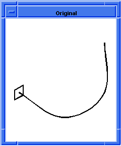
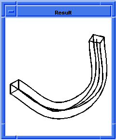
Figure. Sweep with Laws
Sweeping a Screw-Thread
The Scheme example shows how to create a screw using sweeping with laws. One of the first steps is to create a center line for the screw. The center line is used by the wire-body:offset command with a twist law option to create a helix. This helix then becomes the sweep path.
A profile for sweeping is then created. The profile is a rectangle, resulting in an auger type thread. If the profile were a diamond or a triangle shape with the hypotenuse facing away from the center line, the result would be a v-shaped thread cut.
The sweep options include a rail law to specify how the profile is to be oriented as it is swept along a non-planar path.
The profile is then swept along the helix path using the sweep options already established. After sweeping is completed, a cylinder blank is created. The threads can then be subtracted from the cylinder, leaving the auger thread screw.
Scheme Example
| ; sweep:law ; Sweeping is much faster when the silhouette line calculation ; is not always performed. (option:set "sil" #f) ;; #t ; Create a center line around which to create the helix. (define wline(wire-body (edge:linear (position 0 0 0) (position 0 (law:eval "8*pi") 0)))) ;; wline (define path(wire-body:offset wline 5 "x")) ;; path ; Create a profile to be swept. (define p1(edge:linear(position 5 0 0)(position 8 0 0))) ;; p1 (define p2(edge:linear(position 8 0 0)(position 8 3 0))) ;; p2 (define p3(edge:linear(position 8 3 0)(position 5 3 0))) ;; p3 (define p4(edge:linear(position 5 3 0)(position 5 0 0))) ;; p4 (define profile (wire-body (list p1 p2 p3 p4))) ;; profile; profile => #[entity 9 1] ; Create a rail law to specify the orientation of the profile ; as it is swept. (define my_rail (law "vec(-cos(x),0,sin(x))")) ;; my_rail ; Set up the sweep options. (define my_sweep_ops (sweep:options "rail_law" my_rail)) ;; my_weep_ops ; Perform the sweeping using the profile, the helix path, and ; the sweep options that specify the rail law. (define my_sweep (sweep:law profile path my_sweep_ops)) ;; my_sweep ; my_sweep => #[entity 10 1] ; Create a cylinder blank. (define my_cylinder (solid:cylinder (position 0 3 0) (position 0 (law:eval "8*pi") 0) 7)) ;; my_cylinder ; my_cylinder => #[entity 11 1] ; When the screw threads are subtracted (cut out) of the ; cylinder blank, the result is a screw. (define my_screw (solid:subtract my_cylinder my_sweep)) ;; my_screw ; my_screw => #[entity 10 1] ; Render the screw to see the image as a solid. (render) |
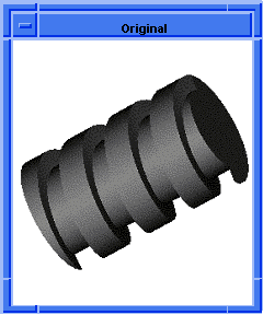
Figure. Sweeping a Screw
[Top]
© 1989-2007 Spatial Corp., a Dassault Systèmes company. All rights reserved.