; Example-1 abl:pos-rad
; Create a solid block.
(define block1 (solid:block
(position -20 -30 -20)
(position 15 30 25)))
;; block1
; OUTPUT Original
; Define the edges.
(define edges1 (entity:edges block1))
;; edges1
; Define which edge to attach the attribute.
(define edge1 (car edges1))
;; edge1
; Define the vertex.
(define vert1 (entity:vertices edge1))
;; vert1
(define start1 (vertex:position
(car vert1)))
;; start1
(define end1 (vertex:position
(car (cdr vert1))))
;; end1
(define rad1 (abl:pos-rad (list start1
(position 15 -5 25)
(position 15 0 25)
(position 15 5 25) end1)
(list 5 10 15 3 1) edge1))
;; rad1
; Put a blend attribute on the selected edge.
(define blend (abl:edge-blend edge1 rad1))
;; blend
; Complete the blend.
(blend:fix edge1)
;; #t
; OUTPUT Result
; Render the result.
(render)
;; ()
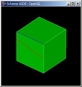
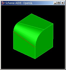
; OUTPUT Rendered Result
Figure. Example-1 abl:pos-rad
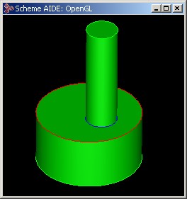
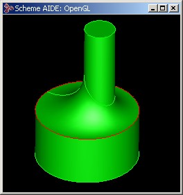
; Example-2 :abl:pos-rad.
; Create the geometry to illustrate command. Create
; a block and a cylinder and unite them.
(part:clear)
;; #t
(define block (solid:block
              (position -20 -20 -20)
	      (position 20 20 20)))
;; block
(define cylinder (solid:cylinder
                 (position 20 0 -20)
	         (position 20 0 20) 20))
;; cylinder
(define united (solid:unite block cylinder))
;; united
; Create a list of all entities.
(define entity-list (part:entities))
;; entity-list
; Get the first entity from the entity list.
(define first-entity (car entity-list))
;; first-entity
; Transform the body.
(define transform (body:get-transform united))
;; transform
; Pick an edge on the body.
(define chosen-one (pick:edge
	           (ray (position 10 -20 100)
                   (gvector 0 0 -1))))
;; chosen-one
; Display it in red.
(define redshoes (entity:set-color chosen-one RED))
;; redshoes
; Get all of the edges that are smooth to the
; selected edge.
(define smooth (blend:get-smooth-edges chosen-one))
;; smooth
; Display them in blue.
(define bluemonday
       (entity:set-color smooth BLUE))
;; bluemonday
; Construct a curve approximating the smooth edges.
(define smooth-curve-list
       (blend:smooth-edges-to-curve smooth))
;; smooth-curve-list
; Find the calibration curve.
(define smooth-curves (car smooth-curve-list))
;; smooth-curves
; Define a position list.
(define positions (list (position -20 -20 -20)
	          (position 20 -20 20)
                  (position 20 20 20)
	          (position -20 20 20)))
;; positions
; Define a radii list.
(define radii-list (list 8 5 5 8))
;; radii-list
; Build the v-radius object.
(if transform (define v-radius (abl:pos-rad positions
	       radii-list smooth-curves transform))
	      (define v-radius (abl:pos-rad positions
	       radii-list smooth-curves)))
;; v-radius
; OUTPUT Original
; Complete the blend.
(define blend (abl:edge-blend chosen-one v-radius))
;; blend
(define complete (blend:network
       (blend:get-network chosen-one)))
;; complete
; OUTPUT Result
Figure. Example-2 abl:pos-rad |