; Use old blending behavior
; do not allow mixed
(option:set "blend_mix_convexity" #f)
;; #t


Figure. 1


Figure. 2
Options |
|
|
|
Technical Article |
||
Options may be set to modify the behavior of ACIS. An option's value
may be a flag (indicating an on/off state), a number (integer or real
number), or a string. Options may be set in a Scheme application (such
as Scheme AIDE) using the Scheme extension option:set;
or in a C++
application using one of several API functions.
|
| Type | Values | Default |
|---|---|---|
| boolean | #f, #t | #f |
| Type | Values | Default |
|---|---|---|
| logical | FALSE, TRUE | FALSE |
Description
If off, this indicates to the entity-entity blending algorithm that
it can assume there are no intersections between the blend sheet and blank
body faces, except for those along the spring curves and any end or side
caps. The benefit is that entity-entity blending will generally work faster
with this option off.
Normally, blend stage two looks out for and computes intersections of the blend faces against remote blank faces (for example, ones that it intersects without the spring curves touching any face boundary), such as isolated bosses that are preserved poking through the blend sheet at the end of the blend. If the user can guarantee that there are no such intersections (usually the case) then this option could be set to off to avoid these checks, sometimes with significant performance gains.
Usually, even if there are remote intersections, turning this option off still allows the blend to work, with the effect of "swallowing" the boss. If, however, the boss is a "handle" and intersects the blank body elsewhere, the blend will fail. Occasionally, if the boss joins the blank completely away from the blend, but part of the boss pokes through the blend from the outside, without touching the blank there, an invalid body will result.
| ; abl_remote_ints ; Turn off remote intersection option (option:set "abl_remote_ints" #f) ;; #f |
[Top]
| Type | Values | Default |
|---|---|---|
| boolean | #f, #t | #t |
| Type | Values | Default |
|---|---|---|
| logical | FALSE, TRUE | TRUE |
Description
With this set to off, blending does not require both sides of a blend
to be actually on their supports, and instead will attempt to cap off
the side that is not on its support.
Note: Applications should not modify this option except when needed for backward compatibility.
| ; abl_require_on_support ; Turn option off (option:set "abl_require_on_support" #f) ;; #t |
[Top]
| Type | Values | Default |
|---|---|---|
| boolean | #f, #t | #f |
| Type | Values | Default |
|---|---|---|
| logical | FALSE, TRUE | FALSE |
Description
When this option is on (true), blending will leave blend attributes on
the blend faces created. These attributes allow later operations to recognize
the faces as blends. For example, local operations will treat such blend
faces as blends, preserving the tangency between the blend face and its
support faces.
Note: Variable radius and Advanced blending blends are not compatible with this option.
| ; add_bl_atts ; Create a blend and leave blend attributes so local ; op will work (define b (solid:block (position -10 -10 -10) (position 10 10 10))) ;; b (define e (pick:edge (ray (position 0 0 0) (gvector 1 0 1)))) ;; e (option:set "add_bl_atts" #t) ;; #f (blend:const-rad-on-edge e 5) ;; #[entity 3 1] (blend:network e) ;; #[entity 2 1] (define f (pick:face (ray (position 0 0 0) (gvector 1 0 0)))) ;; f (define blend_face (pick:face (ray (position 0 0 0) (gvector 1 0 1)))) ;; blend_face ; If add_bl_atts is not on, the local op will fail (lop:taper-faces (list f blend_face) (position 0 0 -10) (gvector 0 0 1) 20) ;; #[entity 2 1] |
[Top]
| Type | Values | Default |
|---|---|---|
| boolean | #f, #t | #t |
| Type | Values | Default |
|---|---|---|
| logical | FALSE, TRUE | TRUE |
Description
If on, this option causes blending (both standard and advanced) to create
the simplest blend possible that gives the same shape as the blend requested.
If the option is off, no blends are simplified.
Note: Applications are strongly discouraged from changing this option.
If the option is on, three blend types can be changed, one in standard blending and two in advanced blending.
| ; blend_make_simple ; Turn off blend simplification (option:set "blend_make_simple" #f) ;; #t |
[Top]
| Type | Values | Default |
|---|---|---|
| boolean | #f, #t | #t |
| Type | Values | Default |
|---|---|---|
| logical | FALSE, TRUE | TRUE |
Description
The blend_mix_convexity option controls the behavior of blending when
edges (to be blended) of different convexity meet at a common vertex.
When the option is set to TRUE, ACIS will attempt to blend this configuration
by adding a vertex blend attribute to the common vertex and then proceeding
normally. When the option is set to FALSE (and there is not a blend attribute
on the common vertex), ACIS will output an error message indicating that
it cannot blend this configuration (this is the default behavior prior
to version 6.1).
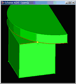
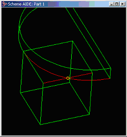
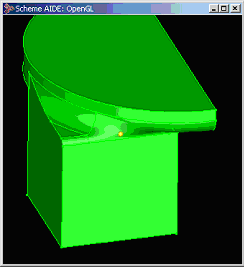
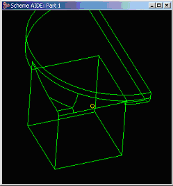
The default value of the option is TRUE. Figure. 1 below is an example of mixed convexity edges sharing a common vertex. The edges to be blended are in red and the vertex is in yellow. The successful blend (with the blend_mix_convexity option set to TRUE) is shown in the next set of pictures (Figure. 2).
| ; blend_mix_convexity ; Use old blending behavior ; do not allow mixed (option:set "blend_mix_convexity" #f) ;; #t   Figure. 1   Figure. 2 |
[Top]
| Type | Values | Default |
|---|---|---|
| real | > 0 | 2.0 |
| Type | Values | Default |
|---|---|---|
| double | > 0 | 2.0 |
Description
Controls the size of the box used by the new capping algorithm for caps
in which it is prepared to explore. Any caps that require exploration
beyond this box will fail. Increasing the value increases the size of
the box, but also the length of time capping may take. The default value
strikes a fair balance between not exploring ludicrously far, but still
successfully completing all but "unreasonable" examples.
| ; bl_cap_box_factor ; Set to 3.0 (option:set "bl_cap_box_factor" 3.0) ;; 2 |
[Top]
| Type | Values | Default |
|---|---|---|
| boolean | #f, #t | #t |
| Type | Values | Default |
|---|---|---|
| logical | FALSE, TRUE | TRUE |
Description
By default, the new capping algorithm (introduced in Release 3.0) is used
by both standard and advanced blending. The new capping algorithm includes
special case analysis to determine the simplest geometry to use. If this
option is turned off, the old capping algorithm is used.
Note: Applications are strongly discouraged from changing this option.
| ; bl_new_capping ; use the old algorithm (option:set "bl_new_capping" #f) ;; #t |
[Top]
| Type | Values | Default |
|---|---|---|
| integer | 0, 1, 2, 3 | 3 |
| Type | Values | Default |
|---|---|---|
| int | 0, 1, 2, 3 | 3 |
Description
This option is not intended for general use, but may be used by customers
that are participating in testing of new blending technology. Customers
should only change the value of this option for testing examples with
the new algorithms.
The valid values are:
0 - Off. Never use the new algorithms (i.e., behave like release 4.x) 1 - On. Reserved for internal use by Spatial Corp. only. Customers should never set this value, as its meaning may change from release to release. 2 - Use the new algorithms only for entity-entity blends. 3 - Use the new algorithms for entity-entity blends, and for the construction of sheet faces in standard blending. > 3 - Reserved for future use.Blending should be regression free only for values equal to or lower than the default setting (excluding the value of 1). As the new algorithms are completed, Spatial Corp. may increase the default value in future releases.
| ; bl_new_technology ; Do not use the new algorithms (option:set "bl_new_technology" 0) ;; 3 |
[Top]
| Type | Values | Default |
|---|---|---|
| boolean | #f, #t | #t |
| Type | Values | Default |
|---|---|---|
| logical | FALSE, TRUE | TRUE |
Description
If on, api_preview_blends
uses the spline approximation of any underlying surfaces in computing
the preview sheet. The default is on. In general, customers should have
not reason to change this.
| ; bl_preview_approx_sf ; Do not use approximations (option:set "bl_preview_approx_sf" #f) ;; #t |
[Top]
| Type | Values | Default |
|---|---|---|
| real | 1.0 ... 20.0 | 8.0 |
| Type | Values | Default |
|---|---|---|
| double | 1.0 ... 20.0 | 8.0 |
Description
This option provides some control over how close (tight) the blend preview
is to the real blend. The default should give good results for most blends,
but if a preview sheet does not seem to agree well with the final result,
then increasing this value may help.
The larger the value, the better the preview, but it can also be slower. Because of the approximations made in generating the preview, there are fundamental reasons why even a "largest tightness" preview will still differ from the true blend.
| ; bl_preview_tightness ; Make preview tighter (option:set "bl_preview_tightness" 10.0) ;; 8 |
[Top]
| Type | Values | Default |
|---|---|---|
| boolean | #f, #t | #f |
| Type | Values | Default |
|---|---|---|
| logical | FALSE, TRUE | FALSE |
Description
A critical portion of the blend algorithm is to detect the interference
of the blend sheet with the geometry of the part being blended. Usually,
interfering geometry can be detected by intersecting the spring curves
of the sheet with geometry local to the blend. Occasionally, the surfaces
of the sheet must be intersected with all of the geometry of the body
to detect such global interferences.
The option bl_remote_ints directs the blending algorithm to perform global or local interference checking. This option is off by default, indicating that the algorithm is to perform local interference checking only. This speeds up blending dramatically in many cases. Although not common, cases do sometimes arise which require global interference checking. If desired, option bl_remote_ints can be turned on, indicating that global interference checking is to be performed.
| ; bl_remote_ints ; Turn on global interference checking (option:set "bl_remote_ints" #t) ;; #f |
[Top]
Description
If this option is on,
autosetback uses api_set_vblend_autoblend,
which allows rolling ball vertex blends to override the autosetbacks.
If this option is off, autosetback uses api_set_vblend_auto,
which always produces a vertex blend n-sided patch in preference
to a rolling ball surface.
[Top]
Description
This option only applies to ACIS Scheme AIDE. If this option is on,
blend previews are shown as the blend attributes are applied.
[Top]
| Type | Values | Default |
|---|---|---|
| string | "min", "max", "old" | "old" |
| Type | Values | Default |
|---|---|---|
| char* | "min","max","old" | "old" |
Description
It this option is set to "min", blending tries to use as few capping faces
as possible. If this option is set to "max", blending tries to use as
many capping faces as possible. If this option is set to "old" (default),
blending tries to emulate the old capping algorithm. Usually this gives
a maximum number of faces solution, but it will give a minimum number
of faces solution if the cap can be started and ended with the same face.
The precise set of heuristics of the algorithm cannot be emulated in all
cases.
Note: Applications are advised against changing this option in order to obtain the best blending results.
| ; cap_preference ; Set to minimum number of cap faces (option:set "cap_preference" "min") ;; "old" |
[Top]
| Type | Values | Default |
|---|---|---|
| boolean | #f,#t | #f |
| Type | Values | Default |
|---|---|---|
| logical | FALSE, TRUE | FALSE |
Description
In many cases, it is preferable for a blend to fail rather than produce
a cap that cuts right across the blend face, or that deletes large portions
of the original body. If this option is off (false), the capping code
will fail in these cases. However, some applications need the capping
code to cap whenever possible. Switching this option on (true) forces
the capping code to cap whenever possible.
| ; force_capping ; Turn option on so capping is always done (option:set "force_capping" #t) ;; #f |
[Top]
| Type | Values | Default |
|---|---|---|
| boolean | #t, #f | #f |
Description
Turning this option on will force all the vertices of a part to be marked
with an "X" (or whatever the current default is for drawing points). Vertices
with blend attributes are drawn in white. The display list must be rebuilt
(use render:rebuild) for it actually to take effect.
| ; show_vertices ; Visually mark vertices of a part. (solid:block (position 0 0 0) (position 10 10 10)) ;; #[entity 2 1] (option:set "show_vertices" #t) ;; #f (render:rebuild) ;; () |
[Top]
| Type | Values | Default |
|---|---|---|
| boolean | #f,#t | #f |
| Type | Values | Default |
|---|---|---|
| logical | FALSE, TRUE | FALSE |
Description
If off, no checks are performed and this behaves like ACIS 4.x. If turned
on, blending may sometimes trap the fact that an illegal surface could
result, and will issue an error instead.
| ; vbl_check ; Turn option on so checks are done (option:set "vbl_check" #t) ;; #f |
[Top]
| Type | Values | Default |
|---|---|---|
| boolean | #f, #t | #f |
| Type | Values | Default |
|---|---|---|
| logical | FALSE, TRUE | FALSE |
Description
If on, reasonably quick checks are performed on the legality of a vertex
blend. If off, no checks are performed.
| ; vbl_quick_check ; Turn option on so checks are done (option:set "vbl_quick_check" #t) ;; #f |
[Top]
| Type | Values | Default |
|---|---|---|
| boolean | #f, #t | #t |
| Type | Values | Default |
|---|---|---|
| logical | FALSE, TRUE | TRUE |
Description
If on, the new algorithm for calculation of the vertex blend boundaries
is used. The new algorithm tries to produce a minimal vertex blend surface
that is legal and well defined using canted cross curves. Rolling ball
vertex blend solutions are used wherever possible.
| ; vtx_blnd_simple ; Turn option on (option:set "vtx_blnd_simple" #t) ;; #t |
[Top]
| Type | Values | Default |
|---|---|---|
| boolean | #f, #t | #t |
| Type | Values | Default |
|---|---|---|
| logical | FALSE, TRUE | TRUE |
Description
Turning this option off suppresses construction of n-sided vertex
blend surfaces, allowing the boundary of the face being made for the vertex
blend to be inspected.
If the boundary is very convoluted or has two adjacent edges meeting tangentially or in a cusp, it is not possible to construct an n-sided blend surface, and the system error BL_NO_VTX_GEOM is returned.
The user can often improve the boundary by changing the blend sizes or setbacks on the blended edges meeting in the blended vertex. To do this, one needs to see what the boundary looks like. To view the boundary, this option should be turned off, and the blend should be repeated, making only the sheet. Attempting to do a fix causes the missing surface to result in the error BL_NO_SHEET_SURF in stage two of blending.
| ; v_blend_nsurf ; Suppress n-sided vertex blend surfaces (option:set "v_blend_nsurf" #f) ;; #t |
[Top]
| Type | Values | Default |
|---|---|---|
| boolean | #f, #t | #t |
| Type | Values | Default |
|---|---|---|
| logical | FALSE, TRUE | TRUE |
Description
If on, the search for a surface to cover the n-sided boundary of
a face to be made for a vertex blend, is broadened to include a rolling
ball surface.
The effect of using a rolling-ball surface is the same as if the blend on the "third" edge above were evaluated (fixed) first, and then a blend was run along the smooth sequence of three edges formed by the other two blended edges with the edge made by the first fix interposed between them.
| ; v_blend_rb ; Turn off rolling ball vertex blend (option:set "v_blend_rb" #f) ;; #t |
[Top]
© 1989-2007 Spatial Corp., a Dassault Systèmes company. All rights reserved.