Tolerant Modeling
Maintaining tight precision yields the best modeling results, but is not always achievable. Tolerant modeling in ACIS increases the scope of the data that ACIS can import. It solves the problems associated with importing inaccurate data or "leaky" models and provides the framework for model healing and data translation.
Tolerant modeling accepts less precise geometric data and creates valid topology. The software attaches tolerance values to edges and vertices, so that even when edges do not intersect within SPAresabs, they're brought close enough to be useful.
Tolerant modeling can also be used to handle approximations for operations that do not require as much precision. Because speed is inversely proportional to precision, ACIS offers users a choice: precision at the cost of speed, or speed at the cost of precision when approximations can suffice. While blending provides support for tolerant or near-tangent models, blending will continue to work best with precise data and, where possible, exact tangencies.
Tolerant modeling does not impact the robustness and reliability of the exact modeling in ACIS. The constructs needed for tolerant modeling are derived from the EDGE, COEDGE, and VERTEX topology classes. Deriving from the base topology elements minimizes the impact to other areas of ACIS. The geometry that describes these tolerant elements and their intersections is same geometry used by the standard elements.
Tolerances are maintained by the system and are updated after each operation with no user input necessary. Users may query the tolerance values, but not set them. The range of testing of tolerant models has been a maximum of about 10 percent of the model size. For example, a block with a height 100, width 100, and depth of 100 has been tested with a tolerant edge with a tolerance of 10.
In the online help, refer also to these related subjects:
- Healing
- Precision and tolerance
- Model topology
Topics include:
How Tolerant Modeling Works
ACIS was developed as an exact modeler, because accurate models are both robust and reliable. A model's geometry, which contains the mathematical definitions describing the intersections, agrees with the topology, which shows how model elements are connected together.
Tolerant modeling does not assume that geometry agrees with the topology, and takes the geometric error in the topology into consideration during modeling operations and calculations.
ACIS uses SPAresabs as a tolerance value for all calculations on an exact model. Tolerant modeling assigns a tolerance value to each tolerant edge and tolerant vertex as part of the topology. This happens only when required to maintain model topology integrity.
For example, imagine a simple rectangular block. This has six faces, 12 edges, and 24 coedges. In an exact model, a coedge of one face references the same underlying geometric definition as a coedge of an adjacent face. There is one edge intersection for both. However, if one of the faces of the rectangular block is not lined up properly with another adjacent face, the pair of associated adjacent coedges do not reference the same underlying geometric definition. The coedge(s) and edge do not represent the same geometric position, and the model is considered "leaky".
The following figure shows the difference between an exact edge and a tolerant edge. The left side of the figure illustrates the exact topology, where the EDGE contains the primary geometric definition and the COEDGE the secondary.
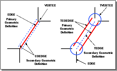
Figure. Exact Edges and Tolerant Edges
In the right side of the figure above, the TCOEDGE contains the primary geometric definition, while the TEDGE contains the secondary.
Tolerant Edges
Tolerant modeling derives a new TEDGE class from EDGE and TCOEDGE from COEDGE, and stores the tolerance as well as the explicit parameterization to limit the edge. The tolerance for the edge is defined as the maximum distance from the 2D parametric coedges of the adjacent faces. The TCOEDGE requires a pcurve and supports a lazy 3D curve.
The tolerance value of a tolerant edge indicates the maximum distance between any two equiparametric positions on any of its tolerant coedges. Two tolerant edges are coincident over an interval if the maximum of the minimum distance between the portion of their point sets bounded by the interval is less than the maximum of the tolerant edge's tolerance values. If the tolerance value is less than SPAresabs, then SPAresabs is used for coincidence checking.
A tolerant edge and an edge are coincident over an interval if the maximum of the minimum distance between the portion of their point sets bounded by the interval is less than the maximum of the tolerant edge's tolerance value and SPAresabs.
A tolerant edge with a single tolerant coedge will have a zero tolerance value. A tolerant edge may only be associated with tolerant coedges.
Non-tangent lateral tolerant edges that have to be extended are also re-intersected to precise geometry. So by tweaking a face to its original surface, non-near tangent tolerant edges can be removed.
Tangent and near-tangent tolerant edges cannot be removed during the local operation but are properly treated by the tweak algorithm. Loops with tolerant edges and vertices are not required to close to within SPAresabs.
Pcurves on tolerant edges are maintained and simplified (when possible) in the tweak operation. When tolerant edges are extended, their underlying pcurves are extended.
Tolerant Vertices
A TVERTEX class that includes a tolerance value is derived from VERTEX. The tolerance value represents the maximum distance from the vertex geometry to the ends of all the adjacent edges that are terminated near the vertex. A tolerant vertex is a 0-dimensional topological entity that is used to bound an edge or a tedge. The topology of an ACIS model remains intact.
Two tolerant vertices are coincident if the distance between their points is less than the maximum of their tolerance values. If the tolerance value is less than SPAresabs, then SPAresabs is used for coincidence checking.
A tolerant vertex and a vertex are coincident if the distance between their points is less than the maximum of the tolerant vertex tolerance value and SPAresabs.
The EDGE class accepts either VERTEX or TVERTEX. An edge might be normal in the sense that it has standard EDGE and COEDGE entities. However, an EDGE might be required to accept one or more TVERTEX entities instead of normal VERTEX entities to create a valid topology.
When solving for a tolerant vertex position, a smart estimate of a solution position is used when curve/surface and curve/curve intersections fail to determine the vertex location.
Options for Tolerant Modeling
These options affect and control tolerant modeling for different operations in ACIS. Review the reference templates before you use them.
Option res_near_tangent
Option res_near_tangent specifies the largest angle in radians that is considered tangent. This option is a system-wide setting for the tolerance to use in testing whether or not an edge is considered tangent (based on the angle between normals). Tolerant modeling algorithms throughout the system may use this value. This option may be used in conjunction with other options that control specific tolerant modeling functionality. For example, this option has no effect on local operations and shelling when lop_tolerant_hot is FALSE.
The value is specified in radians, with a logical range of 0.0 to 2pi. In practice, this will be a small number close to zero.
Option lop_tolerant_hot
Local operations and shelling are only able to create new tolerant geometry when option lop_tolerant_hot is TRUE. Offsetting and shelling create near-tangent tolerant edges in each of the following cases:
- A tolerant edge or a non-tangent edge has its convexity flag marked "tangent." (Algorithms such as blending, lofting, and sweeping will set the convexity flag to "tangent" on edges that the algorithm intended to be tangent, whether tangency is achieved to ACIS tolerances or not.)
- The edge is not tangent but the angle between the surfaces along the edge is less than the value contained in res_near_tangent.
By treating near-tangent edges as tangent, difficult intersections that are likely to be slow and/or fail are avoided between near coincident surfaces.
Option bl_tolerant_hot
The tolerant modeling hot features of blending may be enabled by setting the option bl_tolerant_hot to TRUE. Unless this option is turned on, the blending algorithms will never create a tolerant edge if none was encountered on the blank, even if difficult near-tangencies are involved.
Tolerant Modeling Applications
A number of ACIS functions benefit from using tolerant modeling. Healing, local operations, shelling, and blending use tolerant modeling to solve near tangent edge problems.
In all the examples below, edges that are red are tangent edges, and edges that are blue are near tangent edges that are made tolerant by the local operation. Green edges are neither tangent nor near tangent.
Healing
If HEAL is unable to heal some edges of a model, these edges can be converted to ACIS tolerant edges. Using TEDGEs then allows the body to be used by the tolerant modeling technology. Refer to the reference template for the TEDGE class for more information.
HEAL provides APIs for making these tolerant edges: api_hh_postprocess and api_hh_auto_heal.
Local Operations
All local operations, including tweak, move, taper, shell, offset, and sweep-more, are tolerant modeling friendly. This means that local operations behave sensibly when tolerant geometry is encountered. (The tweak algorithm is the foundation for all other local operations.)
When non-tolerant edge geometry does not lie on adjacent faces to within SPAresabs (indicating a failure earlier in the operation), the edge can be made tolerant to allow the operation to finish. In these cases a tolerant edge is only created when the tolerance will be less than 100.0 * SPAresabs.
When an edge tangent to ACIS tolerance whose geometry is not a line is found between a plane and a cone, the edge is made tolerant and a straight is substituted for the edge geometry. (Mathematically it is easy to prove tangent intersection curves between planes and cones must be lines. Using this fact, local operations is able to simplify model geometry and speed the operation.) Imported data shows this problem where planes and cones do not quite line up.
Non-tangent tolerant edges (or tolerant edges that become non-tangent or non-near tangent in the local operation) are reverted to ordinary edges by using the precise geometry from the intersection of the edge's adjacent surfaces, as shown in the following two figures.
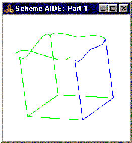
Figure. Before Face Is Moved
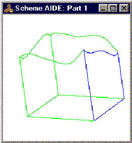
Figure. Lateral Tolerant Edge Reverted to Ordinary Geometry
When a vertex position cannot be determined, the vertex is made tolerant and the operation is repeated before the local operation is allowed to fail.
Shelling and Offsetting
In many cases, creating tolerant near tangent edges in local operations makes shelling and offsetting faster and more reliable. The offset is faster since surfaces adjacent to the near tangent edge do not have to be extended or intersected. The offset is more reliable since near-tangent surface intersections are typically hard and are prone to fail.
The following examples show some of the shelling applications for tolerant modeling.
This model cannot be shelled unless the option lop_near_tangent is TRUE, since the adjacent surfaces on the near-tangent edges (shown in blue) do not intersect.
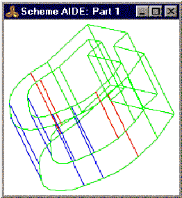
Figure. Swept Model Cannot Shell without Tolerant Modeling
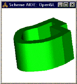
Figure. Shelled with Tolerant Modeling
- Shell characteristics:
- box size is: 12.6 x 16 x 8
- thickness is: 2.0
- tolerance is: 4.3e-12
- res_near_tangent is:0.0175 (about 1 degree)
In the following example, the difficult intersection between the variable radius blend surfaces causes this shell to be significantly slower without tolerant modeling.
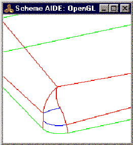
Figure. Variable Radius Blend
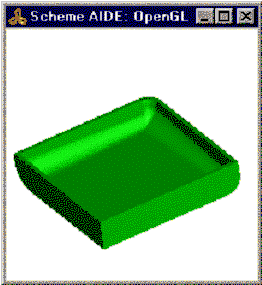
Figure. Shelling with Tolerant Modeling Is Faster
- Shell characteristics:
- 15.89 sec with TM vs. 105.87 sec without TM
- box size is: 11.6 x 11.6 x 2.1
- thickness is: -0.25
- tolerance is: 0.022
- res_near_tangent is: 0.08 (about 4.6 degrees)
Blending
Blending has both "tolerant modeling friendly" and "tolerant modeling hot" features.
Tolerant Friendly Features
Tolerant friendly means that blending algorithms behave sensibly when tolerant edges are encountered. Tolerant modeling friendly features in blending include:
- When a blend rolls over a tolerant edge that connects two faces smoothly, blending will respond by automatically inserting a tolerant edge between the adjacent blend faces that get built.
- Blending rolls straight over a precise but near-tangent edge. Instead of leading to a near-tangent miter with very difficult near-tangent surface intersections, and a concomitantly poor chance of success, this is detected and resolved using a tolerant edge.
- Supporting areas of the algorithms have been augmented to be tolerant modeling friendly. This includes some features in capping, and the Boolean stage of the blend (blend stage two).
These features are always enabled and cannot be disabled. The rationale for this is that if the input part already has tolerant edges in it, and the blend boundaries actually encounter these edges, then it is almost certainly essential that blending will have to construct tolerant edges of its own, or else fail. Tolerant edges are a local feature on a part, however, so if the model contains tolerant edges but the blend does not encounter them, then no new tolerant edges will be created.
Tolerant Hot Features
The blending algorithms will use tolerant modeling when this gives a better route to completing a blend-even when the original part contained only precise edges. This is referred to as being "tolerant modeling hot".
The tolerant modeling hot features of blending are disabled by default. They may be enabled by setting the option bl_tolerant_hot to TRUE. Unless this option is turned on, the blending algorithms will never create a tolerant edge if none was encountered on the blank, even if difficult near-tangencies are involved.
When bl_tolerant_hot is on, the option res_near_tangent controls the maximum angle allowed between two faces along an edge if that edge is still to be treated as "near-tangent". In practice, this means that tolerant modeling will be used to resolve the difficulty, and a tolerant edge is likely to result between the adjacent blend faces there.
The res_near_tangent option is the same option that controls the definition of "near-tangency" for local operations.
As a rule of thumb, res_near_tangent times the blend radius gives an upper bound on the tolerance of any tolerant edges created in a near-tangent situation, so long as that near-tangent edge in the input part is not itself tolerant. If the near-tangent edge is tolerant too, then that tolerance would have to be added in also to get a reliable bound. In practice the blending algorithms usually achieve a much better value those described here.
Scheme Example
; Create a stepped block. (define body (wire-body:points (list (position 0 0 0) (position 0 10 0) (position 0 10 10) (position 0 5 10) (position 0 5 5) (position 0 0 5) (position 0 0 0)))) (sweep:law body (gvector 10 0 0)) (blend:entities body 1.5 'fix) (roll) (edge:tolerant (list-ref (entity:edges body) 1)) (tolerant:move (list-ref (entity:edges body) 1) (gvector 0 -1 0)) (blend:entities body 1.5 'fix) |
[Top]
© 1989-2007 Spatial Corp., a Dassault Systèmes company. All rights reserved.