Booleans
The Boolean Component (BOOL), performs Boolean operations on the model topology of bodies, first finding the intersections between bodies, and then deciding which pieces to group together and which to discard.
A body involved in a Boolean operation may be composed of solid, sheet or wire components. Initial and resulting bodies may be manifold or non-manifold. The results of the Boolean operation may be regularized or non-regularized point sets.
The bodies involved in Boolean operations are often referred to as a blank body and a tool body. The blank body is the body on which to perform the operation and the tool body is the body with which to perform the operation. This is analogous to a "tool" machining portions of a "blank."
There are three basic Boolean operations (illustrated in the following figure):
- Unite
- Creates a body that contains all points that are in either of the two input bodies. This joins the tool body and the blank body.
- Intersect
- Creates a body that contains all points that are common to both of the two input bodies. The result is all points that are in both the tool body and the blank body.
- Subtract
- Creates a body that contains all points that are in the blank body but not in the tool body. This is the difference of the points in the tool body from the points in the blank body.
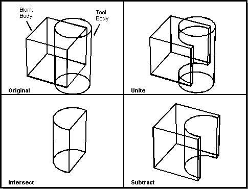
Figure. Boolean Operations
Each Boolean operation (unite, intersect, subtract) is separated into four stages:
- Intersect all of the faces and edges of both bodies and build an intersection graph, which is a data structure defining the intersection of the bodies. This is described in the section Intersection Graph.
- Imprint the intersection graph onto both bodies, often splitting faces in the process.
- Determine what data (for example, faces, shells, and edges) from both bodies to keep and discard, then discard the unnecessary data.
- Join (or un-join) the bodies along the intersection edges, and correctly organize any new shells and lumps.
The Boolean Component also provides a chop operation, which chops the blank body with the tool body. It returns the following bodies: the body formed by subtracting the tool from the blank, and the body formed by intersecting the tool with the blank. Although the same results can be obtained by performing the subtraction and intersection separately, the chop is more efficient. The "leftovers" from the chop can be saved or discarded. The following figure illustrates the chop operation using the Scheme command bool:chop.
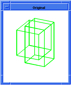
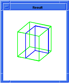
Figure. Chop
This section covers the following Boolean operations:
- Intersection Graph
- Slice
- Imprint
- Regularized and Nonregularized
- Glue
- Fuzzy Booleans
- Open Shell Booleans
- Embedded Faces and Wires
- Partial Booleans
- Selective Booleans
- Non-destructive Booleans
Intersection Graph
The intersection graph is a set of edges and vertices that represent the intersection of two bodies. It contains no shells, but a list of one or more wires. Each wire describes, independently, a connected portion of the intersection between the two bodies. Any two wires are geometrically and structurally disjoint.
For discussion, consider a single wire. The basic constituent of any wire is the edge, which represents a connected bounded portion of a geometric curve; in this case a curve of intersection between two faces, one from each body. The shape of the edge is described in an attached curve record, and the bounds are given by a start and end vertex. The connectivity between edges of the wire is recorded by the use of coedge records attached to the edges.
Each intersection graph edge has one coedge attached to it for each face of each body that passes through the edge. A face is counted twice if it passes right through, appearing on both sides of the edge, and counted once if the intersection lies on the boundary of the face, so that the face is only on one side of the edge. The coedges corresponding to the two intersecting bodies are treated separately.
The edge record points directly to one of its coedges. The coedges are linked together, in a circular list, as partners. When an intersection edge lies within a face of the blank body, it has two coedges, of opposite sense, and may point to either of them. When it lies on the boundary edge of one or more body faces, its coedges correspond in number, sense, and order with those of the body edge. When this would result in all the coedges having the same direction (on an incomplete or sheet body), an additional dummy coedge is added at the end of the loop (that is, immediately before the coedge to which the edge points), with the converse sense. A dummy coedge may be present even if not strictly necessary. An intersection edge coincident with a wire edge of the body has one coedge corresponding to the body coedge, plus a dummy coedge of the converse sense.
Note: To correspond in sense means: If the edges go in the same direction, the intersection graph edge's sense is the same as the body edge's sense. If the edges go in opposite directions, the intersection graph edge's sense is the converse of the body edge's sense (for example, if the body edge's sense is forward, the intersection graph edge's sense is reversed).
An intersection graph edge with no geometry and identical start and end vertices is used to represent an intersection point. If the intersection point lies on a body face, there is one coedge corresponding to that face. If it lies on the interior of an edge, there are two coedges of opposite sense: the forward coedge corresponding to the portion of the edge starting at the intersection, and the reversed coedge corresponding to the portion ending at the intersection. If the intersection point lies on a vertex of a wire of the body, there is one forward coedge for each edge starting there, and one reversed coedge for each edge ending there. Again, if this would result in all the coedges having the same sense, a dummy coedge of the opposite sense is added.
The coedges are linked together at the vertices using the 'previous' and 'next' pointers, corresponding to the start and end vertices, respectively. For each intersection edge, exactly two coedges (one of each sense) have non-NULL pointers, except when a wire is a single open-ended edge, in which case there are no non-NULL pointers at all. When a wire branches at a vertex, the order of connection of the coedges is not important, provided that every edge is visited by the following procedure:
- Select a coedge which ends at the vertex and has a non-NULL "next" pointer.
- Follow the "next" pointer.
- Search the partner ring for the coedge of opposite sense with a non-NULL "next" pointer.
- Repeat from step 2 unless this coedge is the original one.
The "next" and "previous" pointers are complementary: a coedge is always the previous coedge of the next coedge, and vice versa.
Coedges corresponding to faces of the tool body are linked together in exactly the same way, except that in each case the edge does not point directly to one of its tool coedges. Instead, the connection is through an attribute of the edge.
Each topological entity in an intersection wire carries an attribute that relates it to corresponding entities in the original bodies. These attributes contain data essential to the operation of the later stages of Boolean operations, and so must be constructed correctly.
Slice
A slice operation computes the intersection graph between two bodies and creates a wire body corresponding to the graph. This wire body is different from the general intersection graph in that it has two pairs of coedges, one for each of the bodies, that indicate where the edge came from on each body.
Slice can be performed between any model bodies. Any faces and wires within a body, internal or external, can take part in a slice. Slice may also be performed on cellular bodies.
Uses for slice include the generation of waterlines for NC machining or the generation of a cross sectional view on an engineering drawing. These can be done by slicing a solid with a plane. Slice can also be used to provide a profile for:
- Generating new models
- Generating contours to study a shape
- Examining intersections between solids
Imprint
An imprint operation computes the intersection graph of the tool body and the blank body and embeds it into both bodies, splitting faces and edges of the original two bodies with the edges of the intersection graph. The edges and vertices of the intersection graph are added to both bodies wherever edges and vertices do not already exist. If a closed loop of edges is created, a new face is made. An open loop of edges can be added as a spur to an existing loop on a face or as a slit in the face.
Uses for imprinting include:
- Creating edges on a body for subsequent operations, such as sweeping or skinning.
- Visualizing the intersection of two bodies without actually performing a Boolean operation.
- Debugging a Boolean operation.
Regularized and Non-regularized
ACIS provides regularized and non-regularized Boolean operations.
Regularized Boolean operations are performed on the interior point sets, exclusive of the model boundaries. This type of Boolean operation resolves many modeling tangency issues.
Non-regularized Boolean operations include interactions of model boundaries, and leave all boundary coincidences unresolved. This also keeps boundary faces that are internal to a union in the model.
Sheet-Solid and Sheet-Sheet Results
The following table defines sheet/solid and sheet/sheet results for regularized Boolean operations. These operations are the same for wires.
Table. Regularized Boolean Operations
| Operation | Intersecting Bodies | Result |
|---|---|---|
| SUBTRACT | Solid from sheet | Portion of sheet in solid region removed |
| SUBTRACT | Sheet from solid | Portion of sheet within solid interior embedded in solid |
| SUBTRACT | Sheet from sheet (coincident) | Portion of subtracted sheet that overlaps other sheet is deleted (two-dimensional subtract) |
| SUBTRACT | Sheet from sheet (not coincident) | Subtracted sheet deleted |
| UNITE | Solid with sheet | Portion of sheet exterior to solid region added |
| UNITE | Sheet with sheet (coincident) | Two-dimensional unite |
| UNITE | Sheet with sheet (not coincident) | Intersect surfaces and join |
| INTERSECT | Solid with sheet | Portion of sheet interior to solid remains |
| INTERSECT | Sheet with sheet (coincident) | Two-dimensional intersection |
| INTERSECT | Sheet with sheet (not coincident) | NULL body |
Non-regularized Operations
ACIS provides the capability for performing non-regularized Booleans. This is generally implemented by specifying a special argument to a Boolean function. (Scheme extensions may implement separate non-regularized versions, or provide a command option for non-regularized.)
Specifying non-regularized essentially adds three new conditions to the Boolean operations:
- When SINGLE_SIDED faces become DOUBLE_SIDED, BOTH_INSIDE faces, they remain in the resulting body.
- Any face-face coincident region remains in the resulting body.
- No edge or vertex merging is performed at the end of the Boolean.
Due to the first condition, the unite operation always keeps all face regions from the two bodies (although it may split them into separate faces). Due to the second condition, the intersection of two blocks that share a coincident face always leaves the face instead of deleting it. Due to the third condition, subtracting a sheet from a non-coincident sheet leaves the imprint of the subtracted sheet on the other sheet.
The following three figures show examples of regularized and non-regularized Booleans.
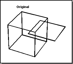
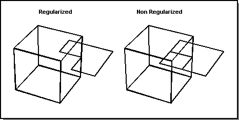
Figure. Regularized vs. Non-regularized Unite
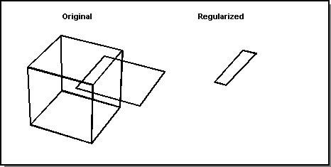
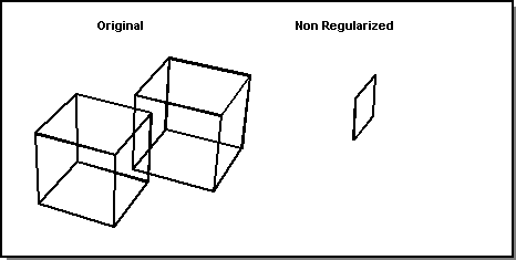
Figure. Regularized vs. Non-regularized Intersect
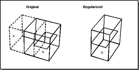
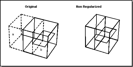
Figure. Regularized vs. Non-regularized Subtract
Glue
Glue operations allow one to perform unite or subtract Boolean operations with increased performance in special circumstances. In particular, glue Booleans can be used when the intersection graph is known to lie precisely on a set of overlapping, coincident faces, and neither body penetrates the faces of the other body.
Intuitively, a glue-unite operation (when non-trivial) can be visualized as "gluing" two solid objects together by pasting their coincident faces.
The performance advantage of a glue Boolean comes from reducing the number of surface-surface intersections performed. Therefore, it may not necessarily be noticed in simple examples, but more likely in cases where there are a large number of coincident faces or the surface geometries are complex.
In order to use glue, all pairs of coincident faces must be identified. In special cases, options can be set for further performance gains. It is essential that this information is accurate and complete, otherwise the results are undefined.
The API used is api_boolean_glue and the Scheme extensions are bool:glue-unite and bool:glue-subtract.
The following scheme script demonstrates how glue can increase performance over a standard Boolean. Please note that timings will vary on individual machines.
|
(define w(wire-body (edge:circular (position 0 0 0) 15))) |
Fuzzy Booleans
Fuzzy Boolean operations allow one to perform Boolean operations on bodies in which some entities (faces or edges) from one of the bodies are intended to be coincident with those on the other body, yet the coincidence is not precise to within resabs. Without fuzzy Booleans, the result of the Boolean would be likely to contain sliver faces, cause performance problems, or even fail completely.
The fuzzy Boolean operations are expected to be particularly useful in situations where the application makes an approximation to a piece of geometry (for instance replacing procedural geometry with its b-spline representation) and then uses the approximation in a Boolean operation with the original exact geometry. This might occur, for instance, when the approximate geometry has been through a translation process, or was generated to simplify the representation but the correspondence with the original geometry has been lost.
To use fuzzy Booleans, the application simply provides a "fuzz" parameter to any of the Boolean operations, passing it in through the BoolOptions object. The fuzz parameter represents a distance within which entities from the different bodies are to be regarded as coincident. If the fuzz parameter is less than resabs, it is ignored.
The Boolean is then carried out and, where entity pairs (for example, edge-face, edge-edge or face-face) are coincident to within the fuzz value, but not within resabs, then the Boolean enforces coincidence by making tolerant entities where necessary. The fuzz value provides an upper bound to any tolerance that is generated. Tolerant entities are only created when absolutely necessary and, when they are created, the tolerance is calculated to be the minimum tolerance necessary to enforce coincidence. Depending on the situation, the fuzz value may be ignored by the Boolean (for instance if forcing coincidence would result in the creation of bad geometry).
The fuzz parameter is set using BoolOptions::set_near_coincidence_fuzz(double) and is returned using BoolOptions::near_coincidence_fuzz(). The Scheme extension for creating and setting Bool options is bool:options and the Scheme Bool option is called "near_coi_fuzz".
Open Shell Booleans
Limited single-sided open shell Booleans are also possible. A single-sided open shell operates like a half-space in a Boolean if it extends beyond the other body on all sides; that is, if the intersection curve lies entirely within the single-sided open shell.
The following two figures illustrate examples of open shell Booleans. The original bodies, which are shown in the following figure, are a planar face (the open shell), which is oriented such that the "inside" of the shell is downward, and a solid sphere, which is positioned such that the planar face intersects it about its equator. The face normals are shown with arrows.
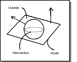
Figure. Open Shell (Planar Face) and Solid Sphere
The following figure illustrates four cases of open shell Booleans with the planar face and solid sphere:
- Subtract the open shell planar face from the solid sphere.
- Subtract the solid sphere from the open shell planar face.
- Intersect the open shell planar face with the solid sphere.
- Unite the open shell with the solid sphere.
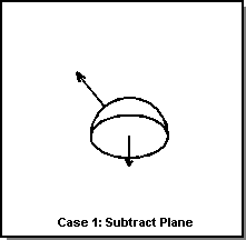
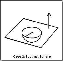
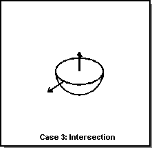
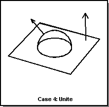
Figure. Open Shell Booleans
Embedded Faces and Wires
Subtracting a sheet from a solid leaves an embedded face, or set of faces, within the solid region. Subtracting a wire from a solid leaves an embedded edge, or set of edges, within the solid region. An embedded face represents a 2D void, sometimes called a "slit," in the solid. Similarly, an embedded edge represents a 1D void, sometimes called a "worm hole," in the solid.
Embedded faces and wires participate in Booleans. During a unite, any embedded face or wire portions in a body that end up inside the other body are removed. A subtraction of a body with embedded faces or wires from a solid body leaves the former embedded faces or wires as external faces or wires.
Partial Booleans
The ACIS implementation of partial Boolean operations allows one to perform "smart" Boolean operations. Partial Boolean operations are more efficient than the standard Boolean operations, because they have prior knowledge about the result. In particular, speed increases are achieved by knowing which faces need to be intersected and, optionally, what the intersection curves are. Two examples in which partial Booleans would provide a speed increase are inserting a pattern of features on a planar face, and modifying the definition of a feature with no topological model changes.
Note: This "selective" partial Boolean functionality is not the same as the functionality implemented in the Selective Booleans Component (SBOOL). SBOOL performs a Boolean operation between two bodies and allows the user to select the regions to keep in the model, using graph theory and cellular topology.
The APIs used for performing partial Boolean operations include:
- api_boolean_start
- This API performs the initial stage of a Boolean operation, initializing the operation to the point where face/face intersections are performed to construct an intersection graph.
-
api_selectively_intersect - This routine is given an array of faces on the tool body which will be intersected with the corresponding face in an array of faces on the blank body. The resulting intersections are appended to the intersection graph (refer to Example 1 below).
-
api_update_intersection - This routine is given a tool face and blank face together with an array of edges, which represent the intersection of the two faces. A surf_surf_int structure is built using the geometry of these edges as the intersection of the two surfaces, thereby eliminating the need to intersect the faces themselves. To record this, an ATTRIB_FACEINT is attached to the tool face and no intersection will be performed when these faces are to be intersected.
-
api_slice_complete - To be used in conjunction with api_selectively_intersect or api_update_intersection. Builds the wire representing the slice after these API functions have been called and the face-face intersections have been computed. Unlike api_complete_intersection_graph the returned slice is not imprintable and the Boolean operation cannot be completed.
-
api_complete_intersection_graph - To be used in conjunction with api_selectively_intersect or api_update_intersection. Builds the wire representing the slice after these API functions have been called and the face-face intersections have been computed (refer to Example 1 below).
-
api_bool_make_intersection_graph - Performs the first stage of the Boolean operation. All face-face intersections are computed and the intersection graph is returned. The intersection graph is represented by a specialized wire body with Boolean attributes so it is ready to be imprinted. This differs from the API api_slice_complete which returns a wire body designed for general use.
-
api_imprint_complete - Imprints the current intersection graph on both bodies. Faces and edges are likely to be split.
-
api_imprint_stitch_complete - This routine imprints the bodies and then stitches them along the face-face intersection curves (imprint edges). It gives the same result as imprinting the two bodies and then stitching them, but is faster because the imprint edges are saved and used directly, instead of detecting compatible edges anew in stitch. Face normals and coedge senses need not be compatible for attempted stitching of open solid-bounding shells along edges. Unlike api_stitch, bodies that do not intersect or touch are grouped into one body anyway.
-
api_boolean_complete - Completes the Boolean operation. Suitable for non-destructive Booleans and glue Booleans (refer to Example 2 below).
-
api_boolean_chop_complete - Completes a chop operation.
Several Scheme extensions demonstrate the use of partial Booleans. The source code for the Scheme extensions is provided to all customers and can be used for examples of implementing partial Boolean operations. The following table shows the APIs called for their corresponding scheme extensions.
| APIs | Scheme Extension |
|---|---|
| api_boolean_start | bool:start |
| api_selectively_intersect | bool:sel-intersect |
| api_update_intersection | bool:update-intersection |
| api_bool_make_intersection_graph | solid:inter-graph |
| api_complete_intersection_graph | bool:complete-inter-graph |
| api_slice_complete | bool:complete-slice |
| api_imprint_complete | bool:complete-imprint |
| api_imprint_stitch_complete | bool:complete-imprint-stitch |
| api_boolean_complete api_boolean_chop_complete |
bool:complete |
Example 1: The First Step of the Boolean operation
Assumptions: blank and tool bodies have already been defined.
| ENTITY_LIST tool_faces; ENTITY_LIST blank_faces; FACE** toolFaceArray = NULL; FACE** blankFaceArray = NULL; // Face counts int toolCount = 0; int blankCount = 0; int intersectionCount = 0; api_get_faces(blank, blank_faces); api_get_faces(tool, tool_faces); toolCount = tool_faces.count(); blankCount = blank_faces.count(); intersectionCount = blankCount * toolCount; // Create and populate FACE arrays toolFaceArray = ACIS_NEW FACE*[intersectionCount]; blankFaceArray = ACIS_NEW FACE*[intersectionCount]; int index = 0; for (int i = 0 ; i { for (int j = 0 ; j { toolFaceArray[index] = (FACE*)tool_faces[i]; blankFaceArray[index] = (FACE*)blank_faces[j]; index++; } } // ***** Now do the Selective Intersection ***** // Initialize boolean result = api_boolean_start (tool, blank); if (!result.ok()) printf("\nError return from api_boolean_start!!"); // Selectively Intersect Faces if (result.ok()) result = api_selectively_intersect(intersectionCount, toolFaceArray, blankFaceArray); if (!result.ok()) printf("\nUnable to selectively intersect entities!!"); // Complete Boolean stage 1 if (result.ok()) { int_graph = api_complete_intersection_graph(tool, blank); // If there is no intersection graph, something is probably wrong if (!int_graph || !int_graph->wire()) sys_error(NO_INTSECT); } if (toolFaceArray) ACIS_DELETE [] STD_CAST toolFaceArray; if (blankFaceArray) ACIS_DELETE [] STD_CAST blankFaceArray; |
Example 2: Usage of api_boolean_complete
This is a non-destructive union preserving both the blank and tool, storing the result in the body res.
Assumptions: The faces to selectively intersect from the blank and the tool bodies have already been inserted in the arrays bfaces and tfaces respectively.
|
Example 3: Locally Intersecting Faces Using Boolean Scheme Commands
| ; First build the bodies to be intersected. (define b1 (solid:block -10 -10 -10 10 10 30)) ;; b1 (define b2 (solid:block -10 -10 0 5 5 10)) ;; b2 (entity:set-color b1 1) ;; () (solid:subtract b1 b2) ;; #[entity 1 1] (define c1 (solid:cylinder 0 0 -20 0 0 50 1)) ;; c1 (define b2 (entity:copy b1)) ;; b2 (define c2 (entity:copy c1)) ;; c2 (entity:transform b2 (transform:translation (gvector 20 0 0))) ;; #[entity 4 1] (entity:transform c2 (transform:translation (gvector 20 0 0))) ;; #[entity 5 1] (solid:unite b1 b2) ;; #[entity 1 1] (define b3 (solid:block 0 0 50 20 1 51)) ;; b3 (solid:unite c1 c2 b3) ;; #[entity 3 1] ; Now the bodies are ready, initialize the Boolean operation. (bool:start c1 b1) ;; #t ; Select the faces to be intersected. (define f_b_0 (list-ref (entity:faces b1) 0)) ;; f_b_0 (define f_b_1 (list-ref (entity:faces b1) 1)) ;; f_b_1 (define f_b_5 (list-ref (entity:faces b1) 5)) ;; f_b_5 (define f_b_6 (list-ref (entity:faces b1) 6)) ;; f_b_6 (define f_t_7 (list-ref (entity:faces c1) 7)) ;; f_t_7 (define f_t_10 (list-ref (entity:faces c1) 10)) ;; f_t_10 ; Perform the local intersections. (bool:sel-intersect (list f_t_7 f_t_7 f_t_10 f_t_10) (list f_b_0 f_b_1 f_b_5 f_b_6)) ;; #[entity 34 1] ; Complete the Boolean operation. (bool:complete "UNION") ;; #[entity 3 1] (entity:check c1 70) ;; checked: ;; 1 lumps ;; 1 shells ;; 0 wires ;; 17 faces ;; 24 loops ;; 80 coedges ;; 40 edges ;; 28 vertices ;; () |
Selective Booleans
The Selective Booleans Component (SBOOL), performs the standard Boolean unite, subtract, and intersect operations. Whereas pure Boolean operations will act upon the full model, selective Boolean operations use graph theory to act upon only selected portions of the model. The sequence of edges or faces encountered in the model is graphed, and ordered pieces of the graph can be tagged for inclusion or exclusion in the result of the Boolean operation.
The selective Boolean operation allows two or more bodies to be combined with greater flexibility regarding what is kept and what is discarded, without having to intersect the bodies more than once. The flexibility in what may be selected is at the cellular level, which allows for more choices than unite, subtract, and intersect.
The two ways of selecting which cells to use are as follows:
- Direct user input of a list of cells that have been picked (the easiest way). For example, in Scheme, this can be achieved by loading pick.scm and then using the pick-cell procedure.
- Analyzing and subsetting the connectivity graph of cells. This uses the graph theory component, which works with and creates graphs.
To make the interactive selection of cells easier, the Graphic Interaction component includes the picking, coloring, and highlighting of cells. To make the programmatic selection of cells easier, the graph theory is used to test, manipulate, and create graphs.
The selective Boolean engine makes use of:
- The non-regular Boolean
- Generic attributes
- Cellular topology
- The ability to 2D convert a body
- The ability to enclose a body
- The ability to regularize a body
- The graph theory component
The following figure shows a blank body consisting of a block with two slots cut out of it and a tool body consisting of a cylinder that penetrates the block in three places. The first stage of the selective Booleans creates a nonregular unite of the two bodies and attaches cellular topology to the result. In addition, the connectivity graph of the resulting cells is returned and the vertices, or cells, of the graph are marked in a way that lets one know which body or bodies they came from.
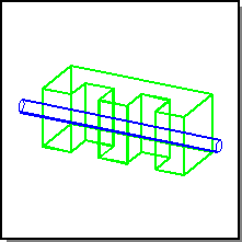
Figure. Blank and Tool Bodies
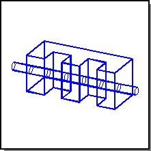
Figure. Blank Body After the First Stage
The resulting body contains eight three dimensional cells, seven that came from the tool body and four that came from the blank body. Three of the cells came from both bodies. The connectivity graph that is returned by the first stage is given in the following figure.
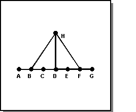
Figure. Connectivity Graph
Cells A through G came from the tool body. Cells B, D, F, and H came from the blank body.
The second stage of the selective Boolean engine takes the nonregular united body and a list or graph of cells. It returns a regularized body that is made up of the given cells or vertices of the graph.
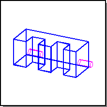
Figure. Result of Picking C, G, and H to Keep
Non-destructive Booleans
By default, the result of a Boolean operation is returned as a modified blank body. The tool body is destroyed. An application may copy one or both input bodies before performing a Boolean operation in order to avoid losing them. However, repeated copying can be expensive in terms of both performance and memory usage.
ACIS provides the ability to perform non-destructive Booleans that preserve one or both input bodies. Examples of when non-destructive Booleans are useful include:
- when the tool body needs to be re-used several times.
- when a body is large but the Boolean operation is relatively small (that is, the area of intersection is very localized), and the body needs to be re-used in a subsequent operation.
This functionality is provided through an optional argument to api_boolean, api_boolean_chop_body, api_boolean_glue, and related partial Boolean APIs. If the blank body is to be preserved, then the caller is responsible for passing in a BODY pointer through which the result will be returned.
[Top]
© 1989-2007 Spatial Corp., a Dassault Systèmes company. All rights reserved.