Refinements
A refinement controls how the facets approximate the solid model and how accurately. A refinement is a C++ class that encapsulates all refining control parameters along with methods to read and modify the parameters. For a complete list of these parameters and their associated methods, refer to the documentation of the class REFINEMENT. Some parameters can take any numeric value (for example, a normal deviation), while others can only take one value of a limited set (for example, surface type and grid handling).
A refinement attached to a face applies only to that face. A refinement attached to a shell, a lump, or a body may apply to the contained faces. Based on the surface type of a face, the refinement is first searched from the face, then the shell, then the lump, then the body, then finally from the faceting defaults. More than one refinements can be attached to an entity with different Surface Mode field in the refinement.
After faceting has determined the applicable refinement for a face, shell, lump, or body during the search, the application is allowed to change the refinement for a face through a method (member function) of the mesh manager. This implies that the application can use some context dependent refinements without going through all the refinements to modify them explicitly.
In general, faceting tries to satisfy all refinement requirements set by the refinement parameters. However, in a case of conflict, higher order parameters will be satisfied and lower order conflicting ones will be ignored. Refinement parameters are considered in the following high to low order:
- Maximum number of grid lines
- Maximum facet edge length
- Normal tolerance
- Surface tolerance
- Grid aspect ratio
The many parameters in the refinement are necessary to provide flexible control. They are used in combinations for the desirable effect.
Default Refinement Values
Default refinement values are set when a refinement is created (for example, when a REFINEMENT class is instantiated). Refer to the class reference template for REFINEMENT for default settings for these refinements:
| Surface Tolerance | Normal Tolerance |
| Grid Aspect Ratio | Maximum Edge Length |
| Maximum Grid Lines | Minimum U Grid Lines |
| Minimum V Grid Lines | Grid Mode |
| Triangulation Mode | Adjust Mode |
| Surface Mode |
|
Refinement values can be queried and set in C++ using various methods of the REFINEMENT class. Refinement values can also be queried and set in Scheme using Scheme extensions (such as refinement:default, refinement:set-default and refinement:set-prop).
Surface Tolerance
The surface tolerance is the distance between the facet and the part of the surface it is representing. By setting this refinement, the user specifies how accurately the facets represent the surface. It is desirable to provide surface tolerance when facets obtained with normal tolerance do not represent the surface well.
The set_surface_tol method from the REFINEMENT class specifies the maximum distance between a facet and the true surface. When this value is positive it is dependent on the model size. If we were to facet using a refinement with mostly default settings, but with a surface tolerance of 0.1, a sphere with a radius of 40 will have many more facets than a sphere with a radius of 1.
The default value of surface tolerance is -1. When the surface tolerance is negative, the faceter uses a surface tolerance that is independent of the model size. The faceter takes the absolute value of this negative number and multiplies it by a fraction (for example, 1/500th) of the diagonal of the bounding box of the body, and uses that number as the actual surface tolerance. For example, when the surface tolerance is set to -10, the faceter uses 1/50th of the length of the diagonal as the actual surface tolerance. Changing the surface tolerance from -1 to -2 (or -5 or -10) results in courser and fewer facets. Changing the surface tolerance from -1 to -0.5 (or -0.2 or -0.1) results in finer and more facets. If the scale of the model grows (or shrinks), the faceting pattern and the number of facets remain the same, but the size of the facets grows (or shrinks). This assumes other refinement controls are not a factor; set the normal tolerance and maximum edge length to 0 to see these differences efficiently. A sphere with a radius of 40 has the same number of facets and same pattern of facets as a sphere with a radius of 1, but the corresponding facets vary greatly in size.
When the value of surface tolerance is 0, this control for faceting is ignored.
The following figure illustrates two cases of surface tolerance. The refinement values are specified below in the following table. In the first case the surface tolerance is zero, meaning that it is not taken into account in faceting. In the second case the surface tolerance is 0.1, meaning that every facet is not more than 0.1 unit away from the mathematical spline surface. In the second case there are smaller but more facets in order to satisfy the surface tolerance constraint.
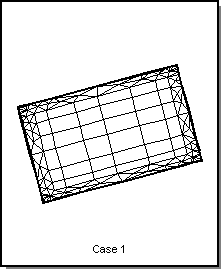
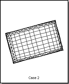
Figure. Surface Tolerance
Table. Surface Tolerance
| Refinement | Case 1 Value | Case 2 Value |
|---|---|---|
| Surface Tolerance | 0 | 0.1 |
| Normal Tolerance | 15 | 15 |
| Grid Aspect Ratio | 0 | 0 |
| Maximum Edge Length | 0 | 0 |
| Maximum Grid Lines | 512 | 512 |
| Grid Mode | AF_GRID_INTERIOR | AF_GRID_INTERIOR |
| Triangulation Mode | AF_TRIANG_FRINGE_2 | AF_TRIANG_FRINGE_2 |
| Adjust Mode | AF_ADJUST_NON_GRID | AF_ADJUST_NON_GRID |
| Surface Mode | AF_SURF_ALL | AF_SURF_ALL |
Normal Tolerance
The normal tolerance is the angle between the surface normals at the two adjacent nodes of a facet. By setting this normal deviation refinement, the user specifies how accurately the facets are representing the surface and the quality of rendering desired. It is desirable to use this refinement control because it is independent of the model size.
The set_normal_tol method from the REFINEMENT class specifies the maximum normal deviation allowed between two normals on a facet edge. The proper value is usually independent of the model size.
The following figure illustrates two cases of normal tolerance. The refinement values are specified in the following table. In the first case the normal tolerance is 15 degrees. In the second case the normal tolerance is 25 degrees, which means that all the adjacent nodes normals have at most a 25 degree angle between them. Because a higher normal tolerance is set, fewer facets are obtained in the second case.
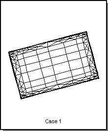
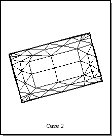
Figure. Normal Tolerance
Table. Normal Tolerance
| Refinement | Case 1 Value | Case 2 Value |
|---|---|---|
| Surface Tolerance | 0 | 0 |
| Normal Tolerance | 15 | 25 |
| Grid Aspect Ratio | 0 | 0 |
| Maximum Edge Length | 0 | 0 |
| Maximum Grid Lines | 512 | 512 |
| Grid Mode | AF_GRID_INTERIOR | AF_GRID_INTERIOR |
| Triangulation Mode | AF_TRIANG_FRINGE_2 | AF_TRIANG_FRINGE_2 |
| Adjust Mode | AF_ADJUST_NON_GRID | AF_ADJUST_NON_GRID |
| Surface Mode | AF_SURF_ALL | AF_SURF_ALL |
Grid Aspect Ratio
The grid aspect ratio is the ratio of the u and v lengths of a uv grid cell. Thus, the aspect ratio is used only when the grid mode is something other than AF_GRID_NONE. The u and v lengths are in object space. The algorithm tries to make the aspect ratio equal to the one specified, but this is not guaranteed.
The grid aspect ratio is defined as the ratio of the geometric length of a grid in the u parameter direction to the geometric length of the grid in the v parameter direction. The faceter attempts to make grids having a ratio specified by the grid_aspect_ratio refinement parameter. For instance, setting the aspect ratio to 1.0 indicates that the grid should be as square as possible. The algorithm which tries to create grids having a specified aspect ratio has been modified to give better grids when the aspect ratio is 1.0.
The set_grid_aspect_ratio method from the REFINEMENT class specifies the approximate aspect ratio of each cell in the grid. If the value is close to 1, then the cell is close to a square. This does not guarantee the aspect ratio of the facet, which may consist of only a part of a cell.
The following figure illustrates two cases of grid aspect ratio. The refinement values are specified in the following table.
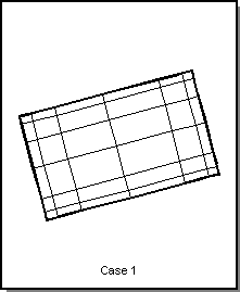
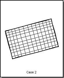
Figure. Grid Aspect Ratio
Table. Grid Aspect Ratio
|
Refinement |
Case 1 Value |
Case 2 Value |
|
Surface Tolerance |
0 |
0 |
| Normal Tolerance | 25 | 25 |
| Grid Aspect Ratio | 0 | 1 |
| Maximum Edge Length | 0 | 0 |
| Maximum Grid Lines | 512 | 512 |
| Grid Mode | AF_GRID_TO_EDGES | AF_GRID_TO_EDGES |
| Triangulation Mode | AF_TRIANG_NONE | AF_TRIANG_NONE |
| Adjust Mode | AF_ADJUST_NON_GRID | AF_ADJUST_NON_GRID |
| Surface Mode | AF_SURF_ALL | AF_SURF_ALL |
Maximum Edge Length
The edge length is the length of a facet edge. The maximum edge length value allows the facet edge length to be within the specified limit. This is the only way to subdivide facets further in planer faces.
The set_max_edge_length method from the REFINEMENT class specifies the maximum length of a side of a cell in object space. Since a facet cannot be larger than the cell, this determines the maximum size of the facet. If the value is zero, maximum edge length is not considered in faceting.
The following figure illustrates two cases of maximum edge length. The refinement values are specified in the following table.
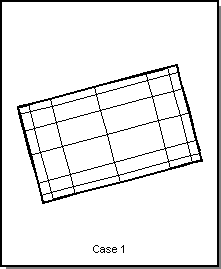
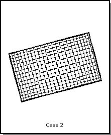
Figure. Maximum Edge Length
Table. Maximum Edge Length
| Refinement | Case 1 Value | Case 2 Value |
|---|---|---|
| Surface Tolerance | 0 | 0 |
| Normal Tolerance | 25 | 25 |
| Grid Aspect Ratio | 0 | 0 |
| Maximum Edge Length | 0 | 2 |
| Maximum Grid Lines | 512 | 512 |
| Grid Mode | AF_GRID_TO_EDGES | AF_GRID_TO_EDGES |
| Triangulation Mode | AF_TRIANG_NONE | AF_TRIANG_NONE |
| Adjust Mode | AF_ADJUST_NON_GRID | AF_ADJUST_NON_GRID |
| Surface Mode | AF_SURF_ALL | AF_SURF_ALL |
Maximum Grid Lines
The maximum number of grid lines can prevent the other constraints from being satisfied, so it is recommended to set it to a high value. This refinement has no meaning when grid mode is set to AF_GRID_NONE.
The set_max_grid_lines method from the REFINEMENT class specifies the maximum number of grid subdivisions. This prevents the facet data of a face from getting too big. It can also be used to specify the exact number of divisions on a face by using it in conjunction with another parameter; for example, a very small normal deviation.
The following figure illustrates two cases of maximum grid lines. The refinement values are specified in the following table. In the second case, although normal tolerance is set to 5 degrees, the maximum number of grid lines set to 20 does not allow normal tolerance to generate enough facets.
The maximum number of grid lines also effects the edge split limit (the maximum number of times an edge may be split to meet faceting tolerances). If an edge does not meet tolerances, it is split in two, and if either half does not meet tolerance, the halves are split in two. This continues until tolerances are met, or until the edge split limit is met. The limit for splitting an edge is derived from the maximum number of grid lines. The derived value is sufficient to meet edge tolerances when the maximum grid lines number is sufficient for meeting tolerances along the surface. In some models, meeting edge tolerances may take excessive time and resources. In these cases this limit insures that excessive faceting will not drain system resources or make the system appear to hang.
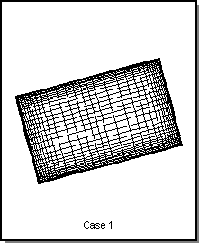
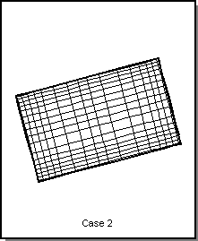
Figure. Maximum Grid Lines
Table. Maximum Grid Lines
| Refinement | Case 1 Value | Case 2 Value |
|---|---|---|
| Surface Tolerance | 0 | 0 |
| Normal Tolerance | 5 | 5 |
| Grid Aspect Ratio | 0 | 0 |
| Maximum Edge Length | 0 | 0 |
| Maximum Grid Lines | 512 | 20 |
| Grid Mode | AF_GRID_TO_EDGES | AF_GRID_TO_EDGES |
| Triangulation Mode | AF_TRIANG_NONE | AF_TRIANG_NONE |
| Adjust Mode | AF_ADJUST_NON_GRID | AF_ADJUST_NON_GRID |
| Surface Mode | AF_SURF_ALL | AF_SURF_ALL |
Grid Mode and Triangulation Mode
The grid mode determines whether a grid is used and whether the points where the grid cuts the edges should be inserted into the edge discretization. The grid mode uses the uv parameter grid of the surface for faceting. Method set_grid_mode of the REFINEMENT class is used to specify the grid mode.
The allowed values are:
- AF_GRID_NONE
- Does not subdivide face with a grid.
- AF_GRID_TO_EDGES
- Uses a grid and creates intersection points of the grid with the edges.
- AF_GRID_INTERIOR
- Uses grid only in the interior. Triangles are generated from the edge to the grid.
- AF_GRID_ONE_DIR
- Uses grid only in the interior. Triangles are generated from the edge to the grid. Nodes are evenly spaced only in the parametric U direction.
The triangulation mode specifies how much triangulation to perform. The set_triang_mode method of the REFINEMENT class is used to specify the mode. If AF_GRID_INTERIOR or AF_GRID_ONE_DIR is specified, triangulation is performed at least at the fringe cells.
The allowable values are:
- AF_TRIANG_NONE
- No triangulation.
- AF_TRIANG_FRINGE_1
- Triangulate at the fringe layer.
- AF_TRIANG_FRINGE_2
- Triangulate two (2) fringe layers.
- AF_TRIANG_FRINGE_3
- Triangulate three (3) fringe layers.
- AF_TRIANG_FRINGE_4
- Triangulate four (4) fringe layers.
- AF_TRIANG_ALL
- Triangulate all facets.
The AF_GRID_INTERIOR and AF_GRID_ONE_DIR mode generates triangles at least near the first fringe, even if the triangulation mode is AF_TRIANG_NONE. In this case, triangulation mode AF_TRIANG_NONE gives the same result as AF_TRIANG_FRINGE_1.
When triangulation mode is set to AF_TRIANG_FRINGE_2, two outermost peripheral grid facets are triangulated. Up to four fringe levels can be specified by the triangulation mode, or AF_TRIANG_ALL can be specified for all triangular facets.
The following figure illustrates three different cases of grid modes and triangulation modes. The refinement values are specified in the following table.
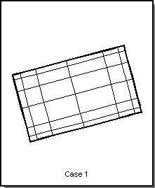
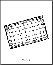
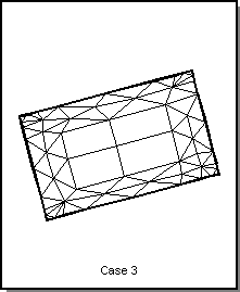
Figure. Grid and Triangulation Modes
Table. Grid and Triangulation Modes
| Refinement | Case 1 Value | Case 2 Value | Case 3 Value |
|---|---|---|---|
| Surface Tolerance | 0 | 0 | 0 |
| Normal Tolerance | 25 | 25 | 25 |
| Grid Aspect Ratio | 0 | 0 | 0 |
| Maximum Edge Length | 0 | 0 | 0 |
| Maximum Grid Lines | 512 | 512 | 512 |
| Grid Mode | AF_GRID_TO_EDGES | AF_GRID_INTERIOR | AF_GRID_INTERIOR |
| Triangulation Mode | AF_TRIANG_NONE | AF_TRIANG_NONE | AF_TRIANG_FRINGE_2 |
| Adjust Mode | AF_ADJUST_NON_GRID | AF_ADJUST_NON_GRID | AF_ADJUST_NON_GRID |
| Surface Mode | AF_SURF_ALL | AF_SURF_ALL | AF_SURF_ALL |
Adjust Mode
The adjust mode works when a uv grid is used along with triangulation of facets. It tries to adjust the facet node positions to smooth the triangles. AF_ADJUST_NONE is default and is preferable for better performance.
The set_adjust_mode method from the REFINEMENT class is used for triangle smoothing. It specifies whether triangles should be smoothed. The nongrid mode preserves the plane of cells by avoiding points that are corners of a cell. The allowable values are:
- AF_ADJUST_NONE
- No smoothing.
- AF_ADJUST_NON_GRID
- Applies to points and not part of a uv cell.
- AF_ADJUST_ALL
- Adjusts all points connected to triangles.
The following figure illustrates two cases of adjust mode. The refinement values are specified in the following table. In the second case, smooth triangles are seen where each node is put in the center of surrounding nodes by iterative algorithm. The AF_ADJUST_NON_GRID option does not show much effect on the triangles.
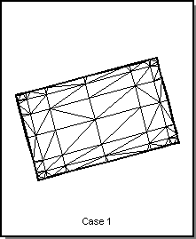
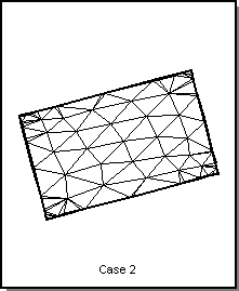
Figure. Adjust Mode
Table. Adjust Mode
| Refinement | Case 1 Value | Case 2 Value |
|---|---|---|
| Surface Tolerance | 0 | 0 |
| Normal Tolerance | 25 | 25 |
| Grid Aspect Ratio | 0 | 0 |
| Maximum Edge Length | 0 | 0 |
| Maximum Grid Lines | 512 | 512 |
| Grid Mode | AF_GRID_TO_EDGES | AF_GRID_TO_EDGES |
| Triangulation Mode | AF_TRIANG_ALL | AF_TRIANG_ALL |
| Adjust Mode | AF_ADJUST_NONE | AF_ADJUST_ALL |
| Surface Mode | AF_SURF_ALL | AF_SURF_ALL |
Surface Type
It is very important to remember the surface type in refinement controls. It is safe to set this to AF_SURF_ALL unless one wants to set different refinement controls for different surface types and attach multiple refinements to the same entity.
The set_surf_mode method from the REFINEMENT class specifies the type of surface to which the refinement is applicable. The allowable types are listed below. If more than one refinement is applicable, the more specific one overrides the less specific one.
- AF_SURF_ALL
- All surface types.
- AF_SURF_REGULAR
- A surface with planar cells ( Plane, Cone, Sphere, Torus).
- AF_SURF_IRREGULAR
- A surface with possibly nonplanar cells (Spline).
- AF_SURF_PLANE
- A planar surface.
- AF_SURF_CONE
- A conical surface (including cylinder).
- AF_SURF_SPHERE
- A spherical surface.
- AF_SURF_TORUS
- A toroidal surface.
- AF_SURF_SPLINE
- A spline surface.
The following figure illustrates two cases of surface type. The refinement values are specified in the following table. The surfaces are the Bsplines surfaces. The surface type for the face in case 2 is AF_SURF_PLANE, so the given refinements are not applied at all. Instead, the ones which were applied earlier (same as in case 1) take effect. Because of this, we do not see the effect of changing the normal tolerance from 25 in case 1 to 5 degrees in case 2.
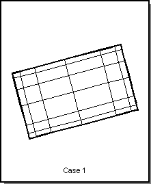
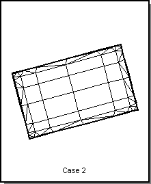
Figure. Surface Type
Table. Surface Type
| Refinement | Case 1 Value | Case 2 Value |
|---|---|---|
| Surface Tolerance | 0 | 0 |
| Normal Tolerance | 25 | 5 |
| Grid Aspect Ratio | 0 | 0 |
| Maximum Edge Length | 0 | 0 |
| Maximum Grid Lines | 512 | 512 |
| Grid Mode | AF_GRID_TO_EDGES | AF_GRID_INTERIOR |
| Triangulation Mode | AF_TRIANG_NONE | AF_TRIANG_FRINGE_1 |
| Adjust Mode | AF_ADJUST_NON_GRID | AF_ADJUST_NON_GRID |
| Surface Mode | AF_SURF_ALL | AF_SURF_PLANE |
Related topics:
Mesh Managers
The Faceting Algorithm
Step-by-Step Faceting
Discarding or Keeping Facet Data
Faceting Functions and Classes
Faceting Using Scheme
[Top]
© 1989-2007 Spatial Corp., a Dassault Systèmes company. All rights reserved.