Assembly Modeling Tutorial
Overview
This tutorial guides the ACIS Assembly Modeling customer through the steps an end-user would follow in order to create, modify, and save an assembly in a typical application. This section provides a concrete framework for introducing the concepts and interfaces that the customer uses within ACIS Assembly Modeling.
Note: Throughout this document, "customer" refers to an application developer writing an ACIS-based application ("the application"), that is, a Spatial customer (or, to be more precise, the person reading this documentation), while "end-user" refers to a user of that application, that is, the customer's customer. Technical details are distinguished by italics.
Topics include:
Assembly vs Part Modeling
One of the first things that the end-user notices when working with the application is that he may choose to work on either an assembly model or a part model. This dichotomy extends to the way in which model information is persisted to disk; most applications have different file-name extensions for assemblies and parts. (ACIS, for example, uses the extensions ASAT and SAT, respectively, to distinguish the two.) If the end-user chooses to work on a part model, he is placed in a context ("part modeling mode") where he manipulates the equivalent of ACIS BODY objects to make a single part. When finished, he saves the data to a part file, the application writing a SAT segment, together with whatever metadata (for example, a feature tree) it associates with the part.
SAT segments are embedded by calling api_save_entity_list on an already open file.
If the end-user chooses to work on an assembly, however, he is placed into a sub-application where he is able to load copies of part models and/or assembly models into memory, position them in space relative to one another, organize them hierarchically into an assembly, and make changes to the way in which the copies of the parts (and/or sub-assemblies) are expressed in the assembly. This context is "assembly modeling mode"; it involves organizing pre-existing content (parts and sub-assemblies) into more complicated structures. When the end-user saves his work, the work is saved in an assembly file, rather than a part file. This file contains an ASAT segment and the assembly metadata. The application may give the end-user the option of saving the entire assembly into a single file (monolithic saves), or breaking it up into multiple files (atomic saves). ACIS (and hence the ACIS-based application) supports this functionality. One of the important responsibilities of the customer's application is to include in the metadata information that allows references between atomic files to be re-bound if any of the files is changed.
Concepts
The following topics discuss the two sets of concepts that have been introduced in this section.
Modeling Modes
Part modeling and assembly modeling perform fundamentally different types of operations. Part modeling creates indivisible units of content (parts), while assembly modeling arranges copies of parts into assemblies. The set of operations performed by the application may thus be subdivided according to mode: part modeling operations are performed in part modeling mode, while assembly modeling operations are performed in assembly modeling mode. This dichotomy is expressed within the ACIS interface through the interface function names; the API functions, with names beginning api_, are used in part mode; functions with names beginning asmi_ are used in assembly mode.
Parts, Assemblies, and Models
An assembly aggregates both parts and sub-assemblies. From the point of view of the high-level assembly structure, there is little difference between the two. For example, the wheel model that occurs in a car might be a part (if the designer does not wish to go into detail about the actual manner in which the wheel is constructed), or the wheel might be a sub-assembly (containing tire and hubcaps, for example). However, the person looking at its image on a monitor, in either case, regards it as "a wheel."
For this reason, we introduce the concept of a model, which is something that can be aggregated by an assembly (for example, "a wheel"). Models come in two varieties: those which contain an assembly (assembly models) and those which do not (part models).
Assembly models may, however, directly contain part data (that is, BODYs), referred to as assembly-level entities. The application can place assembly-level features (for example, weld beads) within an assembly without requiring the creation of a separate model.
In the ACIS Assembly Modeling interface, the assembly object ( ASM_ASSEMBLY) is an aggregation ENTITY that is hidden behind the model object (asm_model). This allows the contents of an assembly to be expressed differently when it is included as a sub-assembly within another model. In turn, the contents of an assembly object do not necessarily represent the "final result" when it is being used as a sub-assembly. (As an example, the containing model may change the color of the sub-assembly, a change that appears only in the context of the containing model.) Interface functions that provide component queries access the ASM_ASSEMBLY object and take any modifications from higher-level assemblies into account, and so are the functions that should be used to read the assembly tree.
Interoperability
In both examples given above (of part and assembly modeling), we assumed that the end-user intends to use his saved models for use in a later session of the application. If he instead wants to use them in a different ACIS-based application, he needs to save the models into a SAT or ASAT file, as appropriate. We strongly recommend that ASAT files written for the purpose of export to another modeler be saved as monolithic, rather than atomic files.
Tutorial
Let us assume that the end-user wishes to design a car: one that contains a body and two axle sub-assemblies. He might proceed as follows:
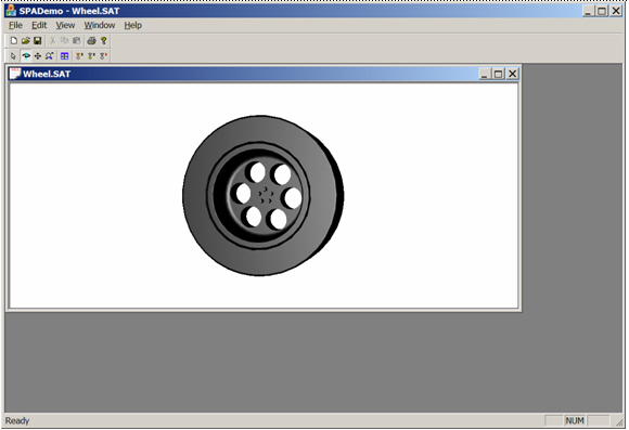
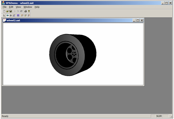
Part 1: Creating a Wheel Part
The end-user creates a wheel part, working in part modeling mode. He begins by opening a new part, which is placed in its own view within the application. Using standard part modeling operations, he goes about designing the wheel, and at the end of the process he has a wheel part that could be saved in the application's native file format, or to a SAT-file if he wants to export it. He also assigns a color to the wheel; this color is a property within the part. He might also specify the type of material for the wheel.
In ACIS Part Modeling, properties such as color and material type are represented by ATTRIB objects attached to the ENTITY being decorated with the corresponding property. The customer typically uses standard part modeling interface functions such as api_rh_set_entity_rgb and api_rh_set_material to accomplish such tasks.
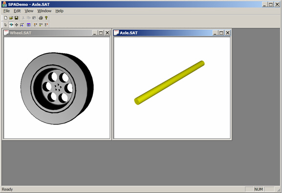
Part 2: Creating an Axle Part
Next, the end-user makes the axle part (not to be confused with the axle assembly). First, he ensures that the diameter of the blind hole in the wheel matches the diameter of the axle. (Note that this is a cross-part constraint, which must be supported by customer code.) Using this radius, he extrudes a cylinder to make the axle part.
At this point, the end-user has two parts (wheel and axle) open in two separate views:
Entity Managers
Note that both the wheel and axle parts each contain a single ACIS
BODY. The pointer to this
BODY is held by a customer object that is associated with the
part. The customer part object can also be bound to views in the customer
application, or collaborate with customer classes that are bound to views. In
other words, a customer part modeling application will have one or more objects
associated with a particular part that manage the
ENTITYs associated with that part (for example, ownership,
rendering, history stream, units, and filenames). This functionality is
provided in ACIS by the ACIS PART object, but many customers use
their own part management code.
For this reason, ACIS Assembly Modeling has introduced an abstract base class asm_model_entity_mgr, through which assembly modeling functions communicate with the customer part objects. Customers who do not use the ACIS part manager and wish to implement assembly modeling operations in their application must derive a subclass of asm_model_entity_mgr that wraps their part object(s). Each asm_model object is bound to a single entity manager, which manages items such as history stream, units, and entity ownership. Customers can choose to derive entity-manager class types for use with assembly models separately from those used with part models; ACIS Assembly Modeling is insensitive to their choice.
| // Create an assembly model bound to the axle's entity-manager asm_model* axle_model = NULL; outcome result = asmi_model_create(axle_entity_mgr, FALSE, axle_model); check_outcome(result); |
Part 3: Creating an Axle Assembly
Next, the end-user makes the axle assembly. To do this, he proceeds as follows:
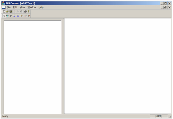
-
The end-user opens a new assembly. This is bound to a third view within the
application.
In ACIS Assembly Modeling, this is done by creating a new model with asmi_model_create (passing in a newly created entity manager), then adding an assembly to it using asmi_model_create_assembly.
// Create the assembly model associated with the axle assembly
asm_model* axle_asm_model = NULL;
outcome result = asmi_model_create(axle_asm_entity_mgr, FALSE, axle_asm_model);
check_outcome(result);
// Add an assembly entity to the model
result = asmi_model_create_assembly(axle_asm_model);
check_outcome(result);
In Scheme, this is done by creating a new part with part:new, wrapping it in a model by calling model:create on the part, then adding an assembly by calling model:create-assembly on the model.
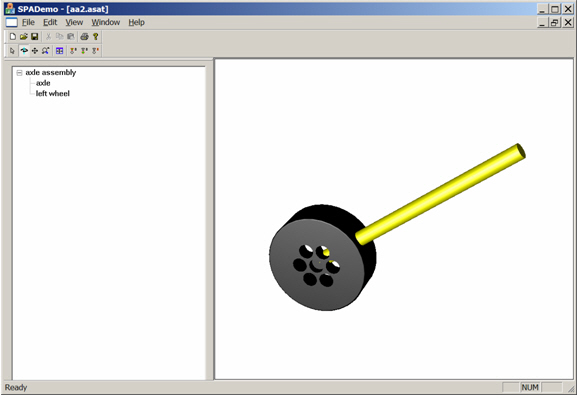
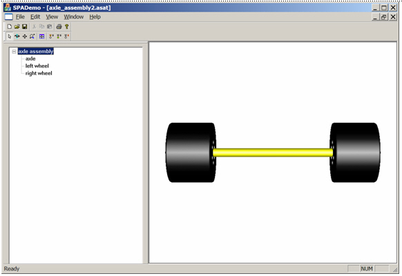
-
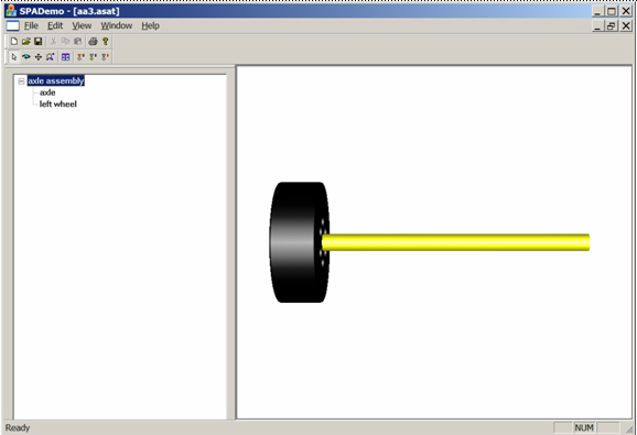
Next, the end-user adds a reference to the axle part to the assembly. An
assembly is a collection of model references (often called instances in other
applications), each of which consists of a pointer to a model plus a transform.
Model references can be thought of as independently positioned copies of a
standard part or sub-assembly. In this case, the standard part is the axle
part.
Note that the assembly tree to the left has an entry called "axle," which corresponds to the model reference ("model-ref") that the end-user just created.
In the ACIS Assembly Modeling interface, the model-ref object ( ASM_MODEL_REF) is, like ASM_ASSEMBLY, derived from ENTITY. Like the latter, therefore, it may be associated with a history stream.
In ACIS, the reference is added by first wrapping the axle part in a model by calling asmi_model_create, then calling asmi_model_add_model_ref, which adds to the axle assembly a reference to the axle part.
// Construct the transform defining the axle reference
SPAtransf axle_transf = ...;
// Create the reference to the axle model
entity_handle* axle_mref = NULL;
result = asmi_model_add_model_ref(axle_asm_model, axle_transf, axle_model, axle_mref);
check_outcome(result);
In Scheme, this is done by calling model:create on the axle part's part object, then model:add-model-ref to add a reference to the axle model into the axle assembly.

-
Next, the end-user adds a wheel to the assembly, in the same way he added the
axle. Notice that there is now a "left wheel" entry in the tree (corresponding
to the reference to the wheel model).
-
At this point, the end-user needs to orient the wheel relative to the axle. He
does this in the application by setting constraints that require the end of the
axle to be coincident with the hole in the wheel.
ACIS Assembly Modeling does not include constraint solving, so the author of the application (that is, you the customer) must determine the transform to be applied to the wheel through your constraint-solving mechanism.
Once the transform is determined, it is applied to the wheel's model-ref by calling either asmi_model_ref_set_transform or asmi_model_ref_apply_transform. Note that the latter adjusts the existing transform, while the former replaces the existing transform.
// Move the wheel into its proper position
SPAtransf new_left_wheel_transf = ...;
result = asmi_model_ref_set_transform(left_wheel_mref, new_wheel_transf);
check_outcome(result);
In Scheme, the transform is applied to the model-ref similarly, using either model-ref:set-transform or model-ref:transform.
-
Now the end-user adds the other wheel using the same procedure. He also saves
his work, and names the assembly "axle assembly."
In ACIS, the model name, along with units and tolerance values, is managed by the customer part object (that is, by the entity manager). Assembly modeling routines are able to query the model (which then passes the query along to the entity manager) for this information using asmi_model_get_info, which returns an asm_model_info object. Each model's model-info is persisted in the ASAT file, and is passed back to the customer during ASAT restore. Note that the interface for specifying/querying the name uses the wchar_t* type, in order to prevent internationalization bugs.
// Get the model-info associated with the axle assembly, and query the model's name
asm_model_info axle_asm_info;
result = asmi_model_get_info(axle_asm_model, axle_asm_info);
const wchar_t* axle_name = axle_asm_info.get_model_name();
In Scheme, the model-info can be queried using the command model:get-info.
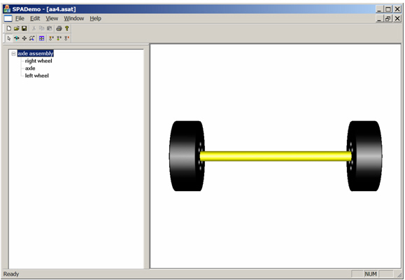
The end-user now has a "right wheel" entry in the assembly tree corresponding to the new model reference. Rather than repeating the phrase "entry in the assembly tree", ACIS Assembly Modeling uses the term "component". In this case of the "left wheel" component, for example, the axle-assembly model is the starting or "root" model of the component and the "wheel" is the "end model."
Altogether four components make up the axle-assembly model's assembly tree: "axle assembly," "axle," "left wheel," and "right wheel." These fall into two categories according to how deeply into the tree they reach: "axle assembly," which is zero levels deep, and the other three, each of which is one level deep. Components belonging to the first category, in which the component is associated with a single model, are generally called model components, while those belonging to the second (for example, "left wheel") are called simple components. Components that are more than one level deep form a third category, and are called compound or complex components.
| // Get the components associated with the axle-assembly model component_handle_list axle_asm_comps; // Specify that all components are to be returned; asm_get_options which(ASM_ALL); result = asmi_model_get_components(axle_asm_model, axle_asm_comps, &which); |
Basically, components name the elements of a model's assembly tree. Additionally, a one-to-one correspondence exists between model components and models (because a model component can be thought of as a pointer to its root model). A one-to-one correspondence also exists between simple components and model references (because each model reference corresponds to a node in the assembly tree).
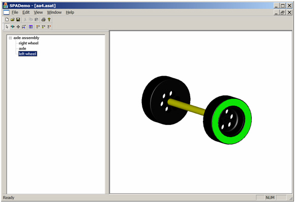
Note also that, although the "axle assembly" contains two references to the wheel model, this does not mean that there are two copies of the wheel model's part data being stored in memory (or on disk). Instead, the model references corresponding to "left wheel" and "right wheel" each represent a recipe for making their pieces of the assembly, based upon the definition of the wheel model (that is, by translating and/or rotating it).
This sharing of models between different components of an assembly is called referencing, which is related to picking. If the end-user tries to pick a face on one of the wheels, he may receive a response such as "face 1 in 'left wheel'" (see below). This is a result of two links to "face 1" (one in "left wheel" and one in "right wheel") in the assembly tree; the result of the pick must specify which component was hit.
Within ACIS Assembly Modeling, a (component, entity) pair is referred to as a component entity and identified by a component_entity_handle pointer (in the same way that ENTITYs are identified by ENTITY pointers).
| // Get the component-entities associated with one component of the
axle-assembly model // Use the first component returned by asmi_model_get_components (above) component_handle* first_axle_asm_comp = axle_asm_components[0]; component_entity_handle_list axle_asm_comp_ents; result = asmi_component_get_component_entities(first_axle_asm_comp, axle_asm_comp_ents); |
Part 4: Creating a Chassis Part
Next, the end-user makes the chassis of the car in a new part.

Part 5: Creating the Car Assembly
Finally, the end-user makes a new assembly to contain the entire model. He accomplishes this task in the same manner he created an assembly to hold the axle.
-
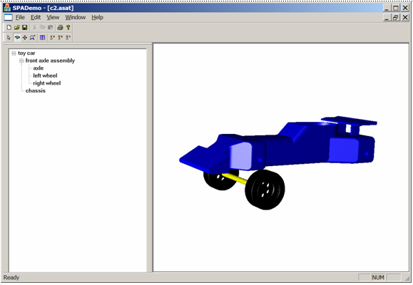
The end-user includes the chassis as the first model reference in the new
assembly.
Note that the assembly tree in this view shows a top-level assembly named "toy car", which has a single component of the chassis named "chassis," corresponding to the chassis model reference.
// Create an assembly model bound to the toy's entity-manager
// Set the create_assembly argument to TRUE, so that an assembly is automatically created
asm_model* toy_model = NULL;
result = asmi_model_create(toy_entity_mgr, TRUE, toy_model);
check_outcome(result);
// Add a reference to the chassis model
SPAtransf chassis_transf = ...;
entity_handle* chassis_mref = NULL;
result = asmi_model_add_model_ref(toy_model, chassis_transf, chassis_model, chassis_mref);
check_outcome(result);

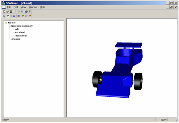
-
Now he includes the front axle assembly in the car assembly. He does this by
making a new model reference referring to the axle-assembly model, just as he
would if he were making a model reference referring to a part.
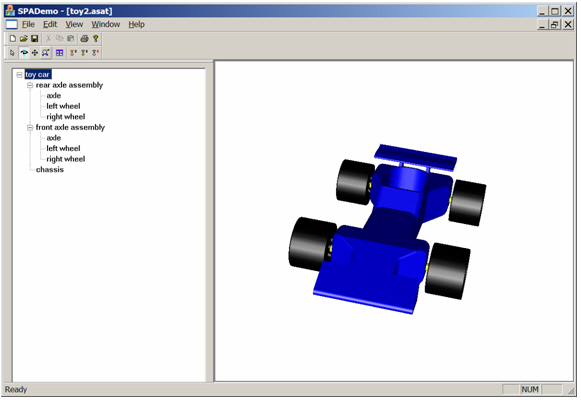
Note that the assembly tree now is multi-level (because of the introduction of the axle sub-assembly.) The top-level assembly "toy car" has two model references, corresponding to "chassis" and "front axle assembly". The axle-assembly model contains three model-refs, corresponding to "axle," "left wheel," and "right wheel" (which are shown in the tree by expanding the "front axle assembly" node).
// Create the front axle assembly component as a reference to axle_asm_model
SPAtransf front_axle_asm_transf = ...;
entity_handle* front_axle_asm_mref = NULL;
result = asmi_model_add_model_ref(toy_model, front_axle_asm_transf, axle_asm_model, front_axle_asm_mref);
check_outcome(result);
-
Next, the end-user orients the axle assembly relative to the chassis by
changing the transform on the model reference corresponding to "front axle
assembly."
// Compose a transform with the existing one to move the front axle assembly into place
SPAtransf add_front_axle_asm_transf = ...;
result = asmi_model_ref_add_transform(front_axle_asm_mref, add_front_axle_asm_transf);
check_outcome(result);
-
The end-user adds another reference to the axle-assembly model to serve as the
rear axle assembly, and orients it relative to the chassis.
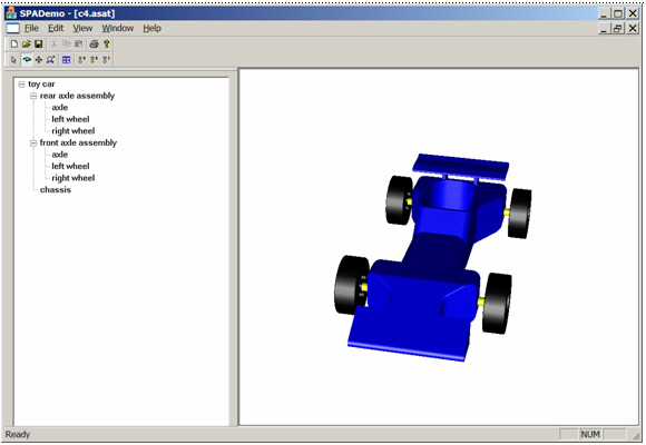
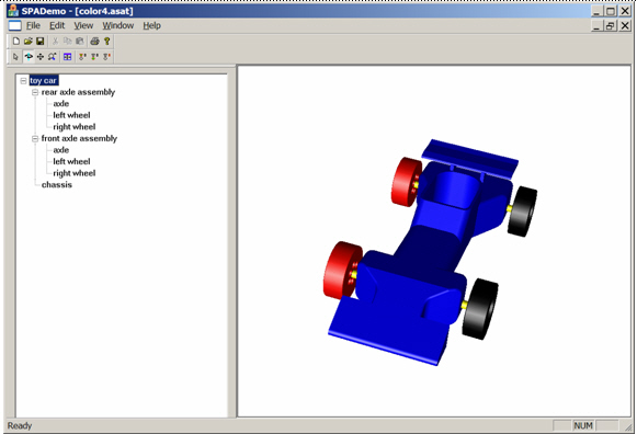
Again, note the assembly tree. The top-level car assembly contains three model-refs, corresponding to the simple components "chassis," "front axle assembly," and "rear axle assembly." Opening either the "front axle assembly" or "rear axle assembly" nodes (components) shows the simple components contained within the axle-assembly model: "axle," "left wheel," and "right wheel."
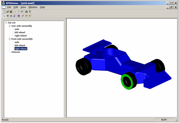
The four wheels of the cart are identified by stringing the simple components together into compound components. For example, the right front wheel corresponds to the "right wheel" component within the "front axle assembly" component; this can be seen from the box drawn in the display when the user picks that node in the tree. Each of the car components (meaning both the physical parts and sub-assemblies that make up the physical car) can be identified by a corresponding entry in the assembly tree.
For this reason, ACIS Assembly Modeling uses pointers to component_handle objects to identify components of an assembly, in the same way it uses pointers to ENTITY objects to identify ENTITYs in a part.
Note that when we speak of "components," we are referring to both parts and assemblies within the physical model (that is, we are over-counting). For example, the car model currently has ten components (seven parts and three assemblies): four wheels, two axles, one chassis, two axle assemblies, and the full car assembly.

ACIS Assembly Modeling provides a component interface, consisting of functions whose names begin with asmi_component_.
In ACIS, in order to reach the wheel's box, call asmi_component_get_box on the component_handle corresponding to the component ("right wheel" in "front axle assembly," in this case). The model-refs that define the component can be obtained from asmi_component_get_path.
// Get the component handle associated with the right front wheel
entity_handle_list right_front_wheel_mrefs;
right_front_wheel_mrefs.add(front_axle_assembly_mref);
right_front_wheel_mrefs.add(right_wheel_mref);
component_handle* right_front_wheel_comp = NULL;
result = asmi_model_get_component_handle(right_front_wheel_mrefs, right_front_wheel_comp);
check_outcome(result);
// Get the wheel's box (default boxing options)
SPAbox right_front_wheel_box;
SPAboxing_options box_opts;
result = asmi_component_get_box(right_front_wheel_comp, right_front_wheel_box, &box_opts);
In Scheme, the box is obtained by calling component:get-box on the selected component, and the model-refs defining a component are obtained from component:model-ref-path.
-
Next, the end-user prefers wider wheels. To make the change, he returns to the
wheel model and changes the width.
This has a cascading effect on the assemblies that include the wheel model. Because the "original" has changed, the model references pass the change along into the assemblies.
-
Next, the end-user decides that he prefers the original wheel width and returns
to the wheel model to make that change.
In ACIS, the customer uses his part modeling mechanisms to allow the end-user to edit the wheel part. After the part modeling session is over, the customer notifies the wheel's model object that the part has changed by calling the contents_changed method of asm_model. This method sends notifications to all models that use the wheel model that something has changed; for example, the models need to discard box caches and re-render.
// Notify all models using the wheel model that its geometry has changed
wheel_model->contents_changed(ASM_BREP_GEOM_CHANGE);
In Scheme, switch to the wheel part and edit it. The acis_scm_entity_mgr, by way of its parent class acis_pm_entity_mgr, distributes the appropriate notifications.
-
Before changing all wheels to gray, the end-user picks one of the wheels with
his mouse, which highlights the component in the assembly tree ("right wheel"
in "front axle assembly" in the figure).
In ACIS, selection is done by calling asmi_raytest_ents, which returns a hit-list containing component_entity_handle pointers (in the same way a part modeling hit-list contains ENTITY pointers). The selected component is the one associated with the first component-entity in the list.
// Fire a ray at the toy model and get the first hit
SPAposition ray_pos(...,...,...);
SPAunit_vector ray_dir(...,...,...);
double ray_radius = ...;
int hits_wanted = 1;
asm_model_list targets;
targets.add(toy_model);
asm_component_entity_handle_list hit_comp_ents;
result = asmi_raytest_ents(ray_pos, ray_dir, ray_radius, hits_wanted, targets, hit_comp_ents);
In Scheme, this is done by calling pick-asm:face, which performs the same steps.
-
With a right-click on a component in the assembly tree (in this case the
right-front wheel), the end-user can set the component's properties. He selects
gray for the color and closes the dialog. The right-front wheel component of
the car (identified by the compound component "right wheel" in "front axle
assembly") is now gray.
In ACIS, this is accomplished by calling asmi_component_set_color on the component_handle corresponding to the selected component. The color can be queried by calling asmi_component_find_color.
// Color the right front wheel gray in the toy model
rgb_color gray(0.5, 0.5, 0.5);
result = asmi_component_set_color(right_front_wheel_comp, gray);
In Scheme, this is done by calling component:set-color and queried by calling component:color on the component Scheme object.
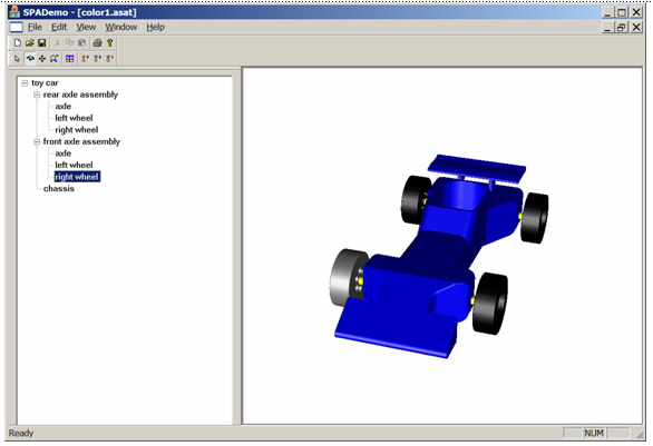
Note that setting the color of the right-front wheel of the car does not change the wheel part (this can be seen by checking the wheel part in the wheel view). In fact, the end-user has already set the color of the wheel body in the wheel part to black (when he first created the wheel). The color change also does not change the axle-assembly model; if it did, then both right wheels would be gray, and we would see a gray wheel in the axle-assembly model. The color is a property that has been applied to the right-front wheel component of the car model and exists only in the car model (and any higher models that include the car as a sub-assembly). This can be further illustrated by returning to the axle-assembly model and applying red to the "right wheel".
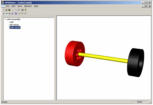
When we return to the car view, we see that the right-rear wheel is now red, but the right-front wheel remains gray.

This occurs because a property (such as color) applied to a component of an owning assembly (for example, gray in the car) overrides a property applied within the owned sub-assembly (for example, red in the axle assembly). When we remove the gray color from the right-front wheel, we see that the red color from the axle assembly is no longer overridden. Thus, both right wheels are red.
ACIS Assembly Modeling has three rules which determine the relative priority of component properties.
Priority Rule 1: The Model in Which the Property Is Applied Is Dominant
Properties applied in higher models always override properties applied in lower models (for example, the car model for "gray" or the axle-assembly model for "red"). This rule is in place because properties are used to modify the way in which existing models are included in an assembly. The properties applied in lower models are part of those lower models; hence, they are subject to modification.
Priority Rule 2: The Property Decorating the Component with the Higher Root Model Overrides the Other
When considering two properties that were applied in the same model, the next criterion concerns the root model of the component to which the property was applied.
Note: Applying properties to components is advanced functionality, exposed through the routine api_asm_component_add_property.
The property decorating the component with the higher root model overrides the other. For example, a color applied to the "right wheel" in a car model is overridden by a color applied to the "right wheel in front axle assembly," because the latter has a higher root model (the car).
Note: Applying a color to the "right wheel" in the car model has the same effect as a color being applied in the axle model, but does not change the axle model.
This criterion is never relevant when working with the component interface functions; the property is applied in the root model of the component.
Priority Rule 3: The Property Decorating the Component with the Lower End Model Overrides Alternative Properties
When the above two criteria are tied in priority, this final criterion resolves how the end model of the component is to be decorated. The property decorating the component with the lower end model overrides alternative properties. For example, setting the color in the car model's "right wheel in front axle assembly" overrides the color set on the car model's "front axle assembly". This rule allows general properties to be set on large groupings of components (an axle-assembly component) which are then overridden by more specific properties applied to particular components within the group (a particular wheel within that axle-assembly component). Note that the advanced interface allows you to find all the properties that have been applied to a particular component if you want to implement different override behaviors. This, however, would be a large task.
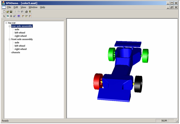
To illustrate this behavior, the end-user decides to color the rear axle assembly green, with red still being applied to the right wheel (in the axle-assembly model). As expected, the green color applied in the car model overrides the red color applied in the axle-assembly model.
The end-user then removes the green from the rear axle assembly, applies gray to the right-front wheel, and applies green to the front axle assembly. The result is a green right-front wheel, because "right-front wheel" is a more specific component than "front axle assembly" (Priority Rule 3 above).

Note that there are four colors competing over the right-front wheel. In order of priority (lowest to highest) they are: black (from the wheel part), red (from the axle assembly), green (from the car model coloring the front axle assembly), and gray (from the car model coloring the front-left wheel).
-
At this point, the end-user decides to remove all component properties except
the gray right-front wheel. He also wants this wheel to be 50%
transparent. Therefore, the end-user sets that property in the same way in
which he set the color.
In ACIS Part Modeling, a property is applied to an ENTITY by attaching an attribute to the ENTITY . Also, standard properties exist for which higher-level interface functions are supplied for creating and attaching the attribute.
In ACIS Assembly Modeling, properties are represented by the same attributes as in ACIS Part Modeling. The difference is that components are decorated with properties, not ENTITYs. The attributes are therefore attached to a proxy ENTITY (for the component) that resides in the model where the property is being applied. In fact, this proxy ENTITY is an attribute that is attached to the ASM_ASSEMBLY in the owning model. As in part modeling, interface functions such as asmi_component_set_transparency and asmi_component_set_color , manage "standard" properties, as well as provide the expert interface for customers who want to define and attach their own property attributes.
// Make the right front wheel 50% transparent in the toy model
result = asmi_component_set_transparency(right_front_wheel_comp, 0.5);
Scheme includes commands for "standard" properties. Non-standard properties are problematic, because ACIS does not have an interface that requests attribute types (in neither assembly modeling nor part modeling).
-
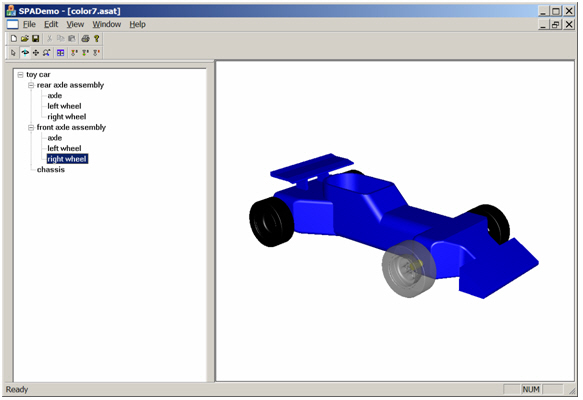
Next, the end-user decides to view the car with the gray wheel removed, that
is, to view the car with only three wheels. To implement this view, the
end-user could either create a new model of the axle assembly that only
contains one wheel, then create a new car that includes a two-wheel axle
assembly at the back and a one-wheel axle assembly at the front or, preferably,
merely suppress the right-front wheel directly. Because ACIS supports
suppression, the latter method is the better choice.

// Suppress the right front wheel in the toy model
result = asmi_component_suppress(right_front_wheel_comp);
The "right wheel" component in the tree has been faded to gray to indicate suppression. Internally (in ACIS), suppression is implemented as with any property. The difference is that suppression is a physical property. It changes, for example, the mass properties of the assembly, while color and transparency merely affect rendering; they only change the appearance of the assembly. Only Spatial may introduce properties that modify the physical properties of the assembly, because ACIS code must be able to recognize the corresponding attributes.
Note: In R17, the only physical properties supported are suppression and mass properties.
The most important concept this example illustrates is that the rendered view of the assembly (which displays the physical components of the assembly) is different from the assembly tree view: the rendered (component) view has three wheels, while the tree view has four (albeit with the suppressed wheel faded to gray). This concept is critical because the natural inclination of developers, when querying the assembly tree, is to write a recursive routine that queries an assembly for its model references, iterates through the model references to get each one's associated model, queries each model for its assembly, then calls itself. This algorithm is equivalent to (naively) walking the tree, and results in incorrect answers when properties have been applied in the assembly (unless the developer searches for the properties that modify each entry within the tree).
For this reason, ACIS Assembly Modeling provides a set of component interface queries (for example, asmi_component_get_sub_components, asmi_component_get_entities, and asmi_component_get_color ) that work with the components of the assembly. In the above example, asmi_component_get_sub_components returns three sub-components when called on the rear axle assembly (two wheels and an axle), but only two when called on the front axle assembly (one wheel and an axle). The suppressed wheel is filtered out by the component query.
To illustrate how one would use the component interface to solve a practical problem, consider the code required to display the car with one wheel suppressed (above). On receiving the request to display the car, the code begins by calling asmi_model_get_components on the car's asm_model, using the ASM_ALL flag to include the root model (the car), then iterates through the resulting list of components (nine in all). Because the sub-components of the assembly components are to be individually rendered, the code only considers ENTITYs that are owned directly by each component's model. Thus, each component calls asmi_component_get_entities to ask the (customer's) entity manager what needs to be rendered. After obtaining the ENTITYs (more precisely, the facets representing the ENTITYs), the code queries the component for its overall location in the assembly model by calling asmi_component_get_transform. ACIS then uses the returned transform to position the ENTITY s' facets. Finally, ACIS queries the component for supported rendering properties (such as color, transparency, and texture), and applies them to the facets.
Summary
As noted above, the purpose of the example is to illustrate why Spatial strongly recommends using the component interface when walking the assembly tree; it is designed to be easy to use and insensitive to the details of how the assembly is represented internally in terms of occurrences, decorations, and model references.
Related topics:
Assembly Modeling Overview
Assembly Modeling vs Part Modeling
Basic Concepts in Assembly Modeling
Properties in Assembly Modeling
Assembly Modeling Save and Restore
Standard Workflows in Assembly Modeling
Assembly Modeling Limitations
[Top]
© 1989-2007 Spatial Corp., a Dassault Systčmes company. All rights reserved.